I am pleased to offer you a set of user oscillators for the Logue platform which I have developed and thoroughly tested over the past few years. These oscillator models run on the Korg Minilogue XD and Prologue, while NTS with its different hardware architecture is currently not supported. The following list can be used to navigate to the reference section for each oscillator type. It is also recommended to read the tech notes, which provide additional information regarding some specifications and usability of the products.
These oscillators are divided into three purchasable bundles:
Basic oscillator collection
Sigma oscillator series, Multi-wave oscillators
Preset oscillator collection
Preset oscillators, One-trick ponies
Sequence oscillator collection
SIGMA oscillator series
SIGMA is the greek letter which is used in math to designate a summation. This oscillator collection is inspired by certain vintage analog synths in which the basic waveforms sawtooth, pulse (or square) and often triangle are used as additive ingredients to form a combined oscillator signal prior to the filter. These waveforms can be regarded as outputs of waveshapers which are phase-locked. To expand the sound palette of SIGMA, the static phase offsets between the basic waveforms can be continuously changed, shifting these waveforms in time. This feature allows for altering the mixed waveform in interesting ways. It also enables the modeling of different phase configurations found in vintage synths.
Finally, a sub oscillator can also be added to the waveform, but unlike in typical analog designs, the sub oscillator constitutes the actual phase reference from which everything else is derived.
SIGMA with phase control comes in three different variants named SIGMA, SIGMA2 and SIGMA3, while a forth version, SIGMA4, omits phase control but offers an additional lowpass filter.
In the following documentation, the term “waveform” is used to actually designate a periodic signal. This terminology is not 100% correct but more convenient.
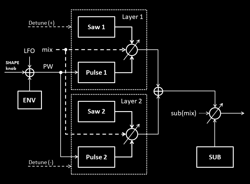
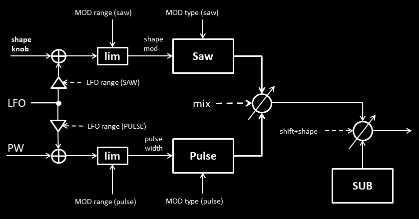
The first version, named SIGMA, mixes five waveforms in a linear fashion to generate the output signal. It contains an attack/decay-envelope (AD-env) for a one-shot modulation of the pulse width (PW). The pulse width can also be modulated using the shape LFO to obtain classic PWM.
The output signal is made up of two layers and the sub oscillator. Each layer consists of a mixture of sawtooth and pulse. Hence, five different waveforms are used in total, denoted as saw1, pulse1, saw2, pulse2 and sub. A simplified signal flow without the handling of phases is shown below.
When SHIFT+SHAPE is set to zero, all waves are phase-locked. In this case, layer1 is identical to layer2, both layers appear as one, and the output signal constitutes just one oscillator as described in the introduction. The phase of the oscillator is reset with every new note-one command (key strike).
When SHIFT+SHAPE is increased up to 50%, layer1 and layer2 are progressively detuned in a symmetrical fashion with respect to twice the sub frequency. Strictly speaking, this constellation is made up of three oscillators in parallel, layer1, layer2 and the sub. The phases are reset with every key, and the sound shows the typical phasing of a sampler or ROMpler playing back two detuned copies of the same sample. The maximum detuning is reached for SHIFT+SHAPE at 50%.
For SHIFT+SHAPE above 50% we enter free-run mode for which the three oscillator phases are not reset anymore, typical for analog synths. From this point, the detuning is decreased and finally reaches 0 for SHIFT+SHAPE set to 100%. At this position, the layers and the sub are phase-locked again, but the layers will experience random phase offsets which vary from voice to voice.
SIGMA: controls
In the following, each input is described. The menu parameters “mix”, “sub”, “modify” and SHIFT+SHAPE are overloaded in the sense that they serve two functions at once, providing a linear value as well as a switch. With these build-in switches, you can choose between four different sub oscillator waveforms (triangle, clipped triangle, square and asymmetric pulse), between left-edge and centered PWM as well as between phase-reset mode and free-run mode.
Note: Before starting to program a patch from scratch,it is recommended to quickly reset the bipolar parameters to 0 as described in the tech notes.
SHAPE
Sets the unmodulated, static pulse width of the pulse waveform between 10% (hard left) and 90% (hard right). Both layers use the same pulse width.
SHIFT+SHAPE
Detunes layer1 and layer2 with respect to the sub as described above. Switches between reset-mode (0-50%) and free-run-mode (50-100%).
SHAPE LFO
The LFO modulates the pulse width.
PAR1: MIX
Range 0%…100% (left-edge PWM):
1. Blends between sawtooth (0%) and pulse (100%) for each layer.
2. Selects left-edge PWM: the positive pulse width changes with respect to its left edge, which is static.
Range -1%-100% (centered PWM):
1. Blends between sawtooth (0%) and pulse (-100%) for each layer.
2. Selects centered PWM: both pulse edges move symmetrically around the static middle-point of the pulse.
PAR2: SUB
Range 0%…100% (sub pulse mode):
Blends between the mix of sawtooth/pulse (0%) and the sub oscillator in pulse mode (100%).
Range -1%-100% (sub triangle mode):
Blends between the mix of sawtooth/pulse (0%) and the sub oscillator in triangle mode (-100%).
Note: to obtain equal amplitudes for sawtooth, pulse and sub, choose mix=+-50% and sub=+-33%.
PAR3: MODIFY
Range 0%…100% (sub standard wave):
1. Changes the phase offsets between sawtooth, pulse and sub.
2. Selects a square wave for the sub in pulse mode, a standard triangle wave for the sub in triangle mode.
Range -1%-100% (sub alternative):
1. Changes the phase offsets between sawtooth, pulse and sub in the same way as for positive values.
2. Selects an asymmetric pulse wave for the sub in pulse mode, a clipped triangle wave for the sub in triangle mode.
Note: the effect of the phase shift is most noticable without detuning.
PAR4: ATTACK [0…100%]
Sets the attack time of the A/D-envelope.
PAR5: DECAY [0…100%]
Sets the decay time of the A/D-envelope.
PAR6: AMOUNT [-100%…100%]
Sets the envelope amount, which can have positive or negative values.
Note: for attack=0, decay=0, the envelope is deactivated.

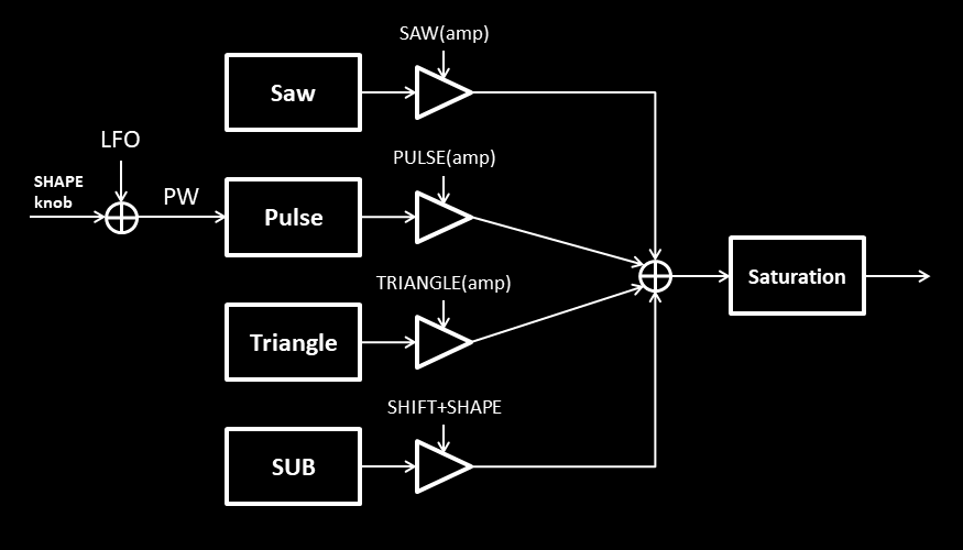
SIGMA2 is a straight-forward implementation of the original idea as described in the introduction. Three phase-locked “components”, sawtooth, pulse, triangle, and also a square sub are used to construct the oscillator waveform. The weighted sum of these components and the sub is fed into a saturator to form the final output signal in the limited range of +-1. For each component you can select the octave, choose one out of two waveforms and set an individual phase offset. The SHAPE LFO can be used to modulate the pulse width. A simplified signal flow without the handling of phases is shown below.
Note: No dedicated envelope is included, but for the XD, the SHAPE LFO can mimic an envelope with attack=0. This can be done by setting the LFO to one-shot-mode, LFO key-sync to ON, LFO voice-sync to OFF and the LFO waveform to SAW.
SIGMA2: controls
All six menu parameters are bipolar and determine a value and a switch state. The sign is equal to the switch state, while the absolute number determines the value, that is -x% is the same value as +x%, namely x.
The positive range is abbreviated as (pos), the negative as (neg).
Note: Before starting to program a patch from scratch,it is recommended to quickly reset the bipolar parameters to 0 as described in the tech notes.
SHAPE
Sets the unmodulated, static pulse width of the pulse waveform between 10% (hard left) and 90% (hard right).
SHIFT+SHAPE
Sets the amplitude of the square sub oscillator between 0 and full-scale.
SHAPE LFO
The LFO modulates the pulse width.
PAR1: SAW
Sets the amplitude of the sawtooth between 0 and full-scale (0…+-100%).
Selects the pitch of the sawtooth: (pos)=main, (neg)=one octave down (sub).
PAR2: PULSE
Sets the amplitude of the pulse between 0 and full-scale (0…+-100%).
Selects the pitch of the pulse: (pos)=main, (neg)=one octave down (sub).
PAR3: TRIANGLE
Sets the amplitude of the triangle between 0 and full-scale (0…+-100%).
Selects the pitch of the triangle: (pos)=main, (neg)=one octave down (sub).
PAR4: PhaseSAW
Controls the phase offset of the sawtooth waveform.
Switches between a sawtooth (pos) and a ramp (neg) by flipping the polarity.
PAR5: PhasePLS
Controls the phase offset of the pulse waveform.
Switches between left-edge PWM (pos) and centered PWM (neg).
For left-edge PWM, the positive pulse width changes with respect to its left edge, which is static. For centered PWM, both pulse edges move symmetrically around the static middle-point of the pulse.
PAR6: PhaseTRI
Controls the phase offset of the triangle waveform.
Switches between a standard triangle (pos) and a clipped triangle (neg).
SIGMA3 omits the triangle wave to have more controls for other functions. The output signal consists of the phase-locked components sawtooth and pulse and a square sub, using a similar topology as for SIGMA, but only for one layer. This version introduces shape mod for the sawtooth waveform in two different variations, borrowed from the TONE oscillator. In addition, each component frequency can be more generally set to some overtone of the sub, not just one octave above. The combined waveform is perceived either as a timbre or more as an interval or chord, depending on the chosen harmonics (overtones) and amplitudes applied via the mix and sub mix setting. To avoid such chords, components set to high overtones should be kept rather small in amplitude.
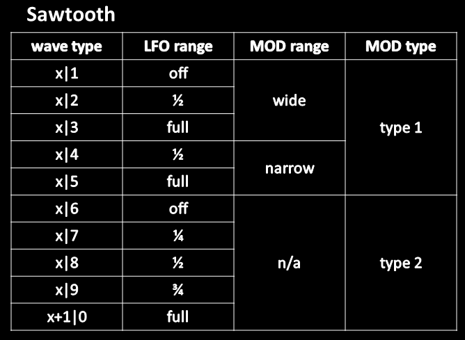
Because there is only one shape LFO as a mod source, the LFO range for pulse modulation (PWM) and sawtooth shape modulation can be individually adjusted, including the choice to switch it off. In addition, the shape mod limit can also be specified between two different ranges. For example for the pulse, you can choose between a pulse width range of 10%-90% or 20%-80%. The idea behind this approach is that when you use PWM for example, the time varying pulse width might bounce against the lower or upper limit, and you might hear the pulse wave with the selected minimum or maximum pulse width for a longer period of time, and, therefore, the limits define the characteristics of such a bouncing sound.
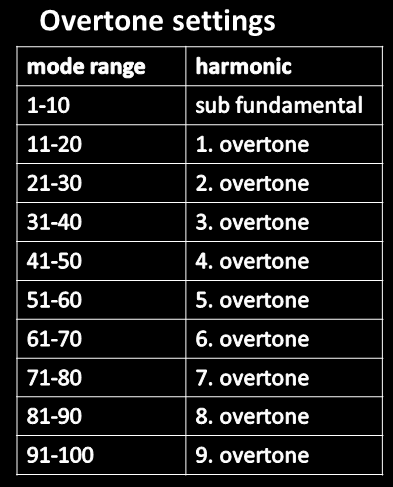
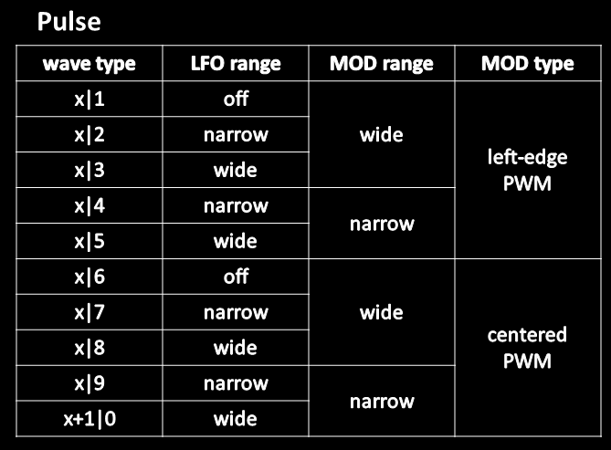
A single mode parameter is used for the sawtooth and another for the pulse to encode a variety of settings, as shown in the following tables. With the exception of the values 10, 20, 30, …, the left digit marks the overtone index (including 0 for the fundamental) and the right digit the “wavetype” for each waveform. The settings for each wavetype are shown in the first and third table. Here, x represents an arbitrary left digit of the mode parameter. The middle table shows the overtone definitions and applies to both waveforms.
Mode parameter encoding
SIGMA3: controls
SHAPE
Sets the unmodulated, static shape of the sawtooth waveform. For the setting hard left, a standard sawtooth is produced.
SHIFT+SHAPE
Blends between the mix of sawtooth/pulse (0%) and the square sub oscillator (100%).
SHAPE LFO
The LFO modulates the shape of the sawtooth and/or the pulse width. This must be enabled by the settings in the sawtooth and/or pulse mode parameters.
PAR1: Mix [0…100%]
Blends between sawtooth (0%) and pulse (100%).
PAR2: PW [0…100%]
Sets the pulse width between minimum (0%) and maximum (100%).
PAR3: ModeSAW [1…100]
Sets the mode for the sawtooth waveform, which is encoded as shown in the first and second table above.
PAR4: ModePLS [1…100]
Sets the mode for the pulse waveform, which is encoded as shown in the second and third table above.
PAR5: PhaseSAW [0…100%]
Controls the phase offset of the sawtooth waveform.
PAR6: PhasePLS [0…100%]
Controls the phase offset of the pulse waveform.
Note: tweaking the phase has it’s strongest effect if two waveforms have the same frequency. If one frequency is much higher, the effect might be hardly noticable.
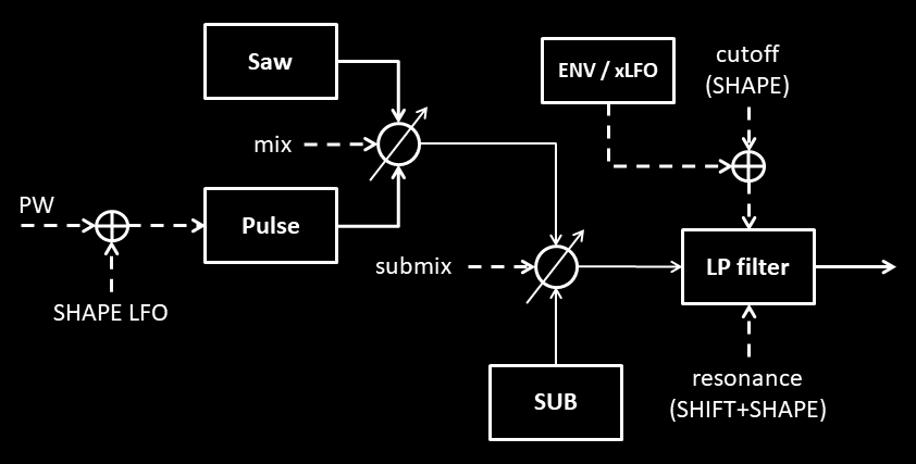
The final oscillator in the series, SIGMA4, is based on a phase-locked trio consisting of a sawtooth wave, a pulse wave, and a square sub-oscillator, utilizing a well-known vintage oscillator configuration. Phase control between the waveforms is omitted in favor of an additional 24 dB/oct lowpass filter with resonance, which requires two additional parameter controls.
The digital filter is borrowed from the SEQ5 oscillator but uses a fixed setting regarding tracking and drive, which appears to be a good musical choice for most cases. Note: to bypass the analog counterpart, select the corresponding post-filter option in the menu. The analog filter can then be fully dedicated to the analog VCOs.
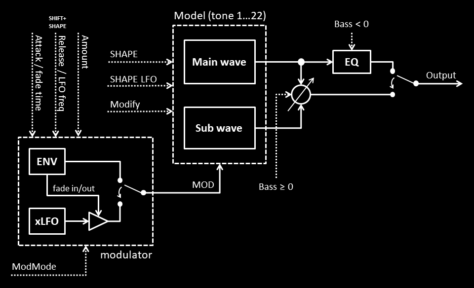
The diagram below illustrates the signal flow of the oscillator. The SHAPE LFO, if active, modulates the pulse width (PW), while the internal envelope (ENV) or extra LFO (xLFO) alter the cutoff frequency, for amounts below or above zero.
Envelope mode for attack < 100%
For attack values smaller 100%, the active internal envelope (ENV) behaves like a standard exponential AD-envelope which is used by many of the oscillators, modulating the cutoff here. When the amount is chosen negative, the envelope is inverted.
Polyphonic LFO mode for attack=100%
If the attack parameter is set to “100%”, the internal envelope is replaced by another LFO (xLFO), which is still assigned to the cutoff frequency. The current release value sets the period length, so that longer release times lead to lower frequencies and vice versa. This is a polyphonic, triangle-shaped LFO which is always restarted at its maximum value when the next note-on command is received. As for the envelope, it’s impact can be inverted using a negative envelope amount.
SIGMA4: controls
To keep things simple, this design does not implement any parameter overloading, except for the ENV/xLFO switch. The numerical range of the first three parameters has been reduced to allow for faster and more responsive control.
SHAPE
Sets the cutoff of the filter. At position hard left (default), the filter is almost closed, resulting in a very quiet sound.
SHIFT+SHAPE
Sets the amount of filter resonance. At position hard left, no resonance is applied.
SHAPE LFO
If activated, the SHAPE LFO modulates the pulse width.
PAR1: MIX [1-41]
Adjusts the mix between the sawtooth wave (min) and pulse wave (max).
PAR2: SUBMIX [1-41]
Adjusts the mix between the main wave combo saw/pulse (min) and the square sub (max).
PAR3: PW [1-41]
Sets the pulse width between 50% (min) and 90% (max).
PAR4: ATTACK [0…100%]
Sets the attack time of the A/D-envelope, or chooses LFO mode for attack=100%.
PAR5: DECAY [0…100%]
Sets the decay time of the A/D-envelope, or sets the period length in LFO mode.
PAR6: AMOUNT [-100%…100%]
Sets the envelope/xLFO amount, which can have positive or negative values.
Note: for attack=0, decay=0, this mod source is deactivated.
Multi-wave oscillators
A “multi-wave oscillator” shall refer to a stacked layer of detuned sawtooth waves or similar waveforms. This kind of oscillator was introduced in the 90ies and and had a great impact on various music styles due to its dense and powerful sound.
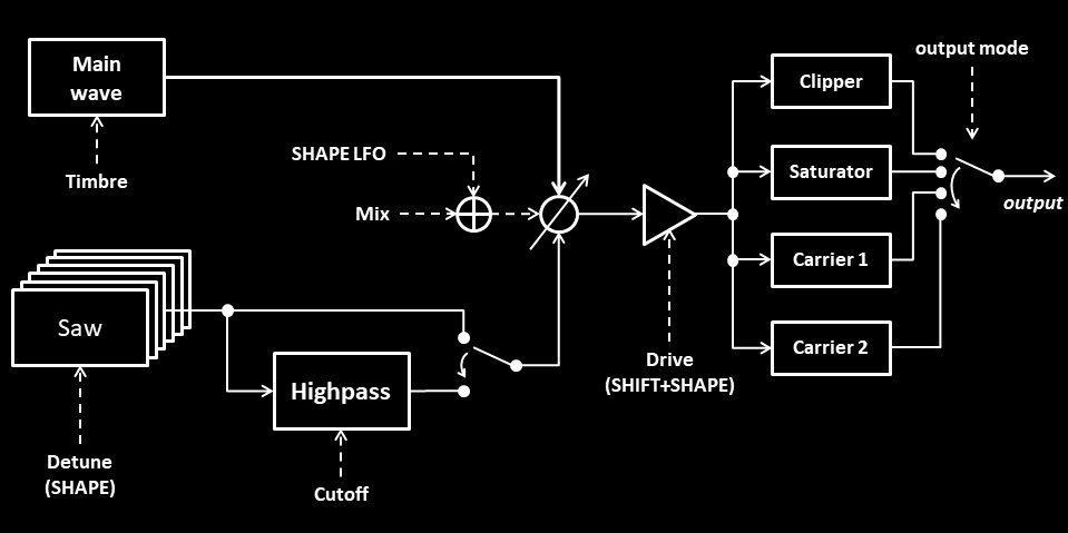
The main oscillator model, called SEVEN, generates one center wave (or main wave) of selectable timbre and six detuned sawtooth waves around it, also denoted as sidewaves. As in the original, the mixture between the center wave and the sidewaves can be adjusted. The oscillator also supports two different detuning patterns, a classic and an alternative one. A detuning pattern defines how much each sidewave is detuned for a rising common detuning factor. Overall, the classic pattern has a wider detuning range. For the main wave you can choose between four different timbres. In addition, four different octave settings exist for the whole constellation.
Also, four different output modes determine how the summed waveform layer is processed before reaching the output. These modes represent different ways to increase the loudness of the signal. Mode 1 uses a clipper, mode 2 a saturator, and mode 3 and 4 make use of a triangle wave – or “carrier” – in different octaves, which is phase-modulated by the seven-tone waveform mix. In general, the achievable maximum loudness increases from mode 1 to mode 2, and from 2 to 3 or 4.
The six detuned sidewaves can be highpassed to reduce loudness fluctuations of the fundamental frequency due to phase cancellations. The center wave is excluded from this thinning process and delivers the base tone of the sound as the highpass is applied more strongly to the sidewaves.
SEVEN: controls
SHAPE
Sets the amount of detuning for the sawtooth sidewaves. The range depends on the chosen detuning pattern.
Note: if you increase the detuning and decrease it back to zero at some point you can get quite appealing sounds for all four output modes. In this case, each voice is static but will sound different.
SHIFT+SHAPE
The function depends on the chosen output mode. For output mode 1 and 2, the knob adjusts the “drive” of the signal into the clipper or saturator. For output mode 3 and 4, it sets the phase modulation amount of the triangle wave. If set to 0 (hard left), only the triangle tone remains, without any modulation.
SHAPE LFO
The LFO modulates the mix between the main wave and detuned sidewaves.
PAR1: Mix [1-11]
Blends between the main wave and the sidewaves. For mix=1, only the main wave remains. For mix=11, all seven waves are equal in amplitude, including the center wave.
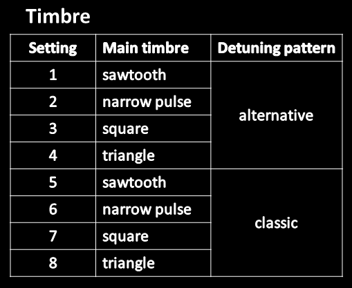
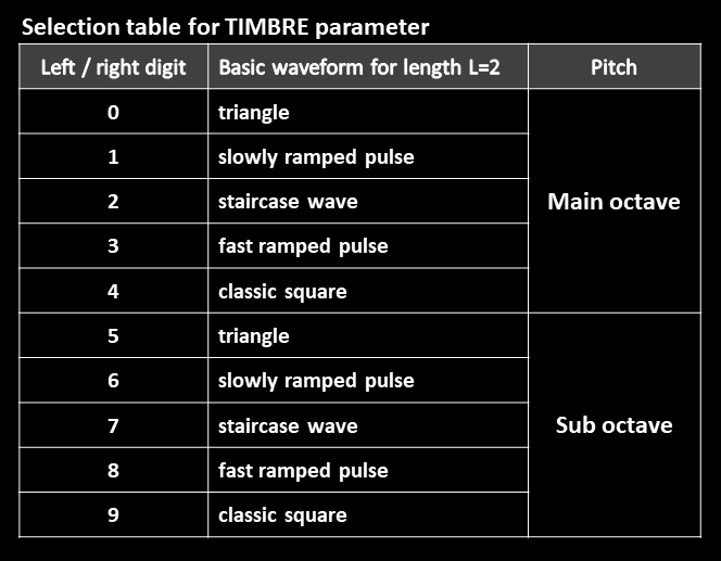
PAR2: Timbre [1-8]
Selects the timbre of the main wave and the detuning pattern for the sawtooth sidewaves according to the following timbre-table. For the main timbre, settings 1-4 are identical to 5-8.
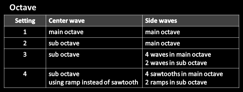
PAR3: Octave [1-4]
Sets the pitch for the main wave and the sidewaves, as shown in the octave-table above. “sub octave” means that a tone is shifted down by one octave. For octave mode 4, the sub waves, consisting of the center wave and two sidewaves, are inverted and played back as “ramps”.
PAR4: OutpMode [1-4]
Selects the output mode of the oscillator. The choices are
1: clipper
2: saturator
3: carrier1
4: carrier2
For clipper and saturator, SHIFT+SHAPE sets the drive for the oscillator signal.
For carrier1 and carrier2, SHIFT+SHAPE defines the amount of phase modulation applied on the carrier, with the multi-wave acting as the modulator. Carrier1 is a triangle wave generated in the main octave while carrier2 is a triangle generated in the sub octave.
PAR5: Highpass [1-11]
Sets the cutoff of the highpass filter applied to the sidewaves. For higher values, more lows are cut out. For a value of 1, the highpass filter is completely bypassed. For other values 2-11, the filter is activated and the output also attenuated by 6 dB to account for the additional headroom required.
PAR6: Slop [1-24]
Sets the amount of random pitch variation between voices. As you reach the maximum, the tuning appears to be rather wonky.
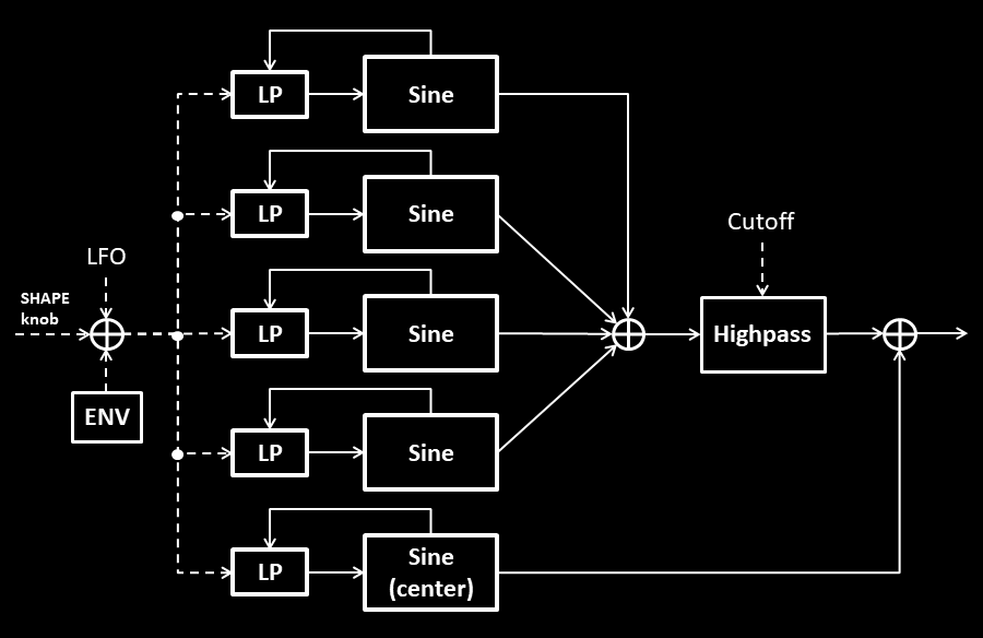
FIVE is the “little brother” of SEVEN, as it creates only five waves. Instead of generating sawtooth waves directly, it utilizes five sine waves with phase modulation feedback — a technique known from FM synthesis. When the feedback is increased, the “warm”-sounding sine waves gradually transform into sawtooth waves, increasing the brightness of the sound. This allows oscillator brightness to be adjusted before reaching the analog filter, either manually, via the shape LFO, or using a dedicated envelope. In some cases, bypassing the analog filter for this digital oscillator may be preferable, freeing the filter for use with the analog oscillators. The generated sound is very smooth, but cannot be “crunched” for some loudness increase. The sound level can still be increased in the usual way by turning up the gain of the entire patch by a maximum of 6 dB, using the menu.
The diagram below shows the signal flow. The combined SHAPE value controls the gain and cutoff of lowpass filters in the feedback paths. It should be noted that the combined SHAPE value is not bounded to zero and can experience positive or negative values. The sound becomes brighter as the SHAPE value deviates more from zero, in either direction. This might be confusing at first. Unlike the scheme used in SEVEN, the generated waves have a fixed amplitude distribution without a mix-option.
FIVE: controls
SHAPE
Controls the brightness of the sound. The maximum is reached at the right position.
SHIFT+SHAPE
Sets the cutoff of the highpass applied to the (detuned) sidewaves. As the knob is turned right, the sidewaves are gradually thinned out.
SHAPE LFO
The LFO also modulates the brightness, just like the SHAPE knob and the envelope.
PAR1: detune [0-100%]
Sets the degree of detuning for the sidewaves. Each wave has its own individual detuning factor.
PAR2: octave [1-2]
Sets the pitch of the center wave in terms of octave position. For octave=1, this wave has the standard pitch. For octave=2, the pitch is shifted one octave down. Sidewaves always have the standard pitch assigned.
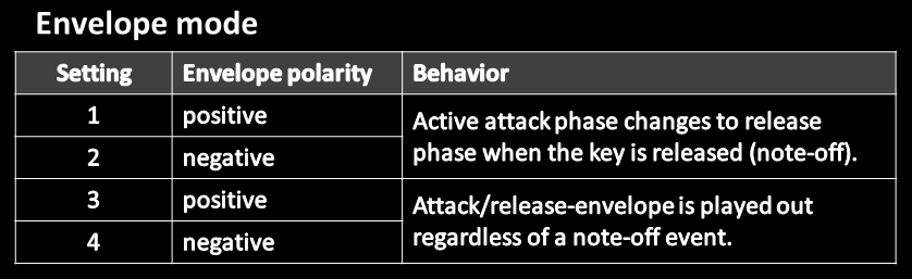
PAR3: envmode [1-4]
Defines the mode of the envelope according to the following table.
Note: The behavior for settings 1 and 2 is the most commonly encountered, but the other is also interesting and useful.
PAR4: attack [0-100%]
Sets the attack time of the A/D-envelope.
PAR5: decay [0-100%]
Sets the decay time of the A/D-envelope.
PAR6: amount [0-100%]
Sets the envelope amount. The polarity is chosen via the envelope mode.
Preset oscillators
The products in this series are based on the same concept: integrating a larger set of different, relatively fixed oscillator models into a single user oscillator. These modes are easily selectable and work much like presets. Each model, on its own, does not involve too much tweaking. For some products, the different oscillator models are embedded into a common outer framework which can provide additional modulation sources and/or post-processing stages.
The minimalistic TONE oscillator can serve on its own or as a supplemental oscillator for the existing analog VCOs, offering basic waveforms in high audio-quality. But it also includes many alternative waveforms to be explored. Each waveform can be manually modified using two controls, SHAPE and modify.
For this oscillator, each model is called a tone in the menu. A tone can be made to sound warmer or fuller by applying either an internal low-shelf filter or a sub-oscillator. The idea behind the first option (EQ) is that the analog filter, with its resonance, can be opened more before sounding harsh and generally reacts a bit differently to a tamed oscillator.
TONE also includes a flexible modulator (MOD) which can either work as an envelope (ENV) or LFO. The LFO shall be called xLFO to distinguish it from the standard SHAPE LFO. This xLFO can be used to perform audio-rate modulation, can operate statically or with a fade-in or fade-out, and can also optionally be locked to the oscillator’s frequency or a fraction of it. The LFO waveform is either a triangle or a sine, depending on the chosen model (tone).
When the xLFO is locked and has a frequency equal either to the main pitch or is transposed by one or two octaves down, the resulting waveform will remain in tune, although optionally transposed. This approach greatly extends the synthesis possibilities as the modulation can be used to change the timbre. Using fade-in or fade-out for the xLFO leads to evolving sounds and expands the possibilities further.
TONE: operation and controls
This section provides a reference for the operation and the controls of TONE. Note that when you change the envelope mode in the menu, this change applies not immediately but for the next active voice. The only bipolar parameter used is Bass. You may want to reset it immediately to 0 when beginning to programm a new patch, starting with an uncolored sound. This reset procedure is described in the tech notes.
SHAPE
Acts as the first modifier for the currently selected tone (waveform).
SHIFT+SHAPE
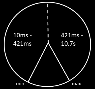
The modulation mode is selected with ModMode. When the modulator works in envelope mode, SHIFT+SHAPE sets the release time of the envelope, shown in the first diagram below.
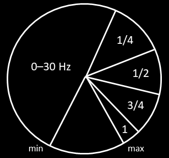
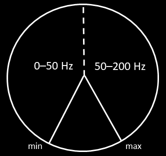
When the modulator works in LFO mode, SHIFT+SHAPE sets the xLFO frequency (2. and 3. diagram). Using the ModMode-parameter, two different frequency ranges for SHIFT+SHAPE can be selected. The first range includes a slow zone ranging from 0 to 30 Hz and a locked zone where the xLFO is locked to the pitch or fraction of the pitch of the oscillator. For example for “1/4”, the xLFO swings two octaves below the oscillator frequency. Range 2 covers frequencies from 0-200 Hz.
Use of SHIFT+SHAPE-knob
SHAPE LFO
For most (but not all) models, the SHAPE LFO controls the same parameter as the SHAPE knob and the modulation source (ENV or xLFO). Details are provided in the model description.
PAR1: Tone [1…22]
Selects the oscillator model. A description of the models is given here.
PAR2: Bass [-100%…+100%]
Parameter to increase the warmth or weight of the sound, or just to add a “solid” fundamental.
Range -100% to 0%: The lower the value, the more the spectrum is boosted in the lows while keeping the overall level nearly constant. The maximum effect is achieved at -100%.
Range 0% to 100%: The main oscillator signal is accompanied by a sub-oscillator. This parameter controls the mix between the main and sub tone. The type of sub-oscillator depends on the model. At 100%, only the sub tone remains.
PAR3: Modify [0…100%]
Acts as the second modifier for the currently selected tone (waveform).
PAR4: ModMode [1…24]
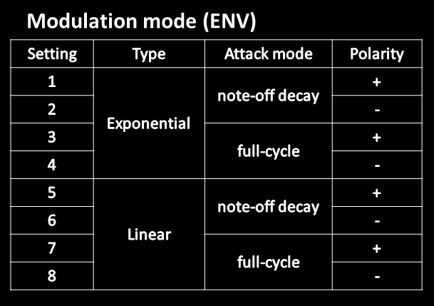
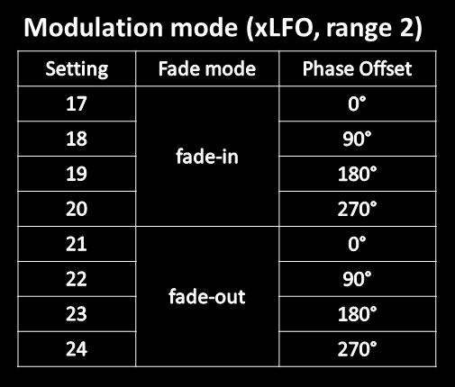
This parameter determines the type and behavior of the modulator (MOD). Modes 1-8 select the envelope (ENV), modes 9-16 the xLFO with range 1 and modes 17-24 the xLFO with range 2. The envelope release range and xLFO ranges are defined here.
For the envelope, you can choose between positive and negative polarity, exponential or linear shape, and either an envelope where an active attack phase switches to the release phase when the key is released, or a full-cycle envelope that maintains the attack phase until the end, regardless of note-off. This results in 2x2x2=8 combinations shown below.
For the xLFO, you can choose between fade-in and fade-out and four different start offsets, again resulting in 2×4=8 combinations for each range.

The xLFO, when in free-run mode, always resets its phase upon striking a new key (note-on). In this case, the phase offset simply defines the starting position. In locked mode, the chosen phase offset of the xLFO is permanently maintainted in relation to the phase of the main wave.
PAR5: Amount [0…100%]
Adjusts the intensity of the modulator (MOD as ENV or xLFO).
PAR6: Attack [0…100%]
In envelope mode, this parameter adjusts the attack time, with slower attacks at higher values.
In LFO mode with fade-in, it defines the fade time, with longer transitions at higher values.
In LFO mode with fade-out, it defines the fade time, but with shorter transitions at higher values. In this mode, when attack is set to 0% the fade-out has no effect.
TONE: OSC models
This section describes the implemented oscillator models, or tones, which represent different types of waveforms. These waveforms are altered in various ways using the first modifier, SHAPE, and the second modifier, MODIFY (PAR3).
Default configuration
It is convenient to introduce a default configuration, allowing the models to be described in a much more compact way. The following points, which are used most often, apply to a model unless otherwise specified:
By default, …
- the modulator and the SHAPE LFO affect the same waveform property which is determined by the static SHAPE knob.
- a square wave is used as a sub, one octave below the main waveform.
- MODIFY affects the phase shift between the main wave and the sub wave.
- the triangle waveform is used for the xLFO.
Tone 1: sawtooth with flipped section (+ square sub)
This model uses a sawtooth wave which is flipped within a certain section of the waveform cycle. SHAPE defines the width of this section, starting at zero. The model is somewhat similar to the analog VCOs operating in sawtooth mode but works in the same octave and leads to different results.
Tone 2: sawtooth with flipped section + square wave
Same as for tone 1, but uses a square wave for bass in the same octave, not one octave below.
Tone 3: sawtooth hard-synced
This model uses a pitched-up sawtooth oscillator that is synced to the standard pitch by resetting its phase with each waveform period. This allows for the reproduction of typical hard sync sounds. SHAPE sets the amount of up-shifting of the oscillator pitch.
Tone 4: sawtooth squeezed
A sawtooth wave is squeezed into a smaller fraction of the waveform cycle as SHAPE increases, while the remaining portion is nulled. The effect is somewhat similar to a high-pass filter but produces a distinct sound.
Tone 5: phase-modulated sawtooth, triangle/square sub
In this simple model, a sawtooth wave is phase-modulated by SHAPE. MODIFY is used to define the sub waveform by fading between a triangle and a square wave, starting with the triangle. The xLFO, if activated, uses a sine wave instead of a triangle wave.
An audible, useful effect is achieved in different ways. One way is to mix the main wave with the sub. The SHAPE knob, SHAPE LFO or the modulator can be used to slowly change the phase shift and achieve a “fatter sound” through the fluctuating spectrum.
Another way is to apply the xLFO at audio-rate frequencies. If the xLFO is locked, the waveform basically remains in tune while new timbres can be generated, similar to phase-distortion synthesis. SHAPE or the SHAPE-LFO can be used to statically change or slowly vary the timbre since the phase shift between the xLFO and the main wave is modified.
Note: if the sawtooth is used naked without the sub and without modulation, SHAPE has no lasting effect.
Tone 6: two phase-modulated sawtooths (+ square sub)
In this model, two sawtooth waves are phase-shifted simultaneously using SHAPE. MODIFY determines the individual phase shift intensities for sawtooth 1 and sawtooth 2. The xLFO, if activated, uses a sine wave instead of a triangle wave.
For MODIFY=0%, the sawtooths are equally phase-shifted in opposite directions with rising SHAPE. As MODIFY is increased, the phase shift intensity is reduced for sawtooth 1 and increased for sawtooth 2. For MODIFY=100%, all phase shifting is performed for sawtooth 2 while sawtooth 1 remains static.
In addition, the phase offset for the sub is also changed with rising MODIFY. The impact of MODIFY becomes clear when the waveform is blended with the sub and/or the xLFO performs audio rate modulation.
Tone 7: one static and two phase-modulated sawtooths
Three sawtooth waves are mixed together. Wave 1 is static while wave 2 and 3 are phase-modulated using SHAPE. Wave 2 has a fixed modulation intensity while wave 3 uses a variable modulation intensity adjusted with MODIFY. A square sub can be added in the usual way.
For MODIFY=0%, wave 3 has a maximum positive modulation intensity. As MODIFY is increased, this intensity is decreased, approaching zero for MODIFY=50%. Finally, at MODIFY=100%, wave 3 sees a maximum negative modulation intensity.
Tone 8: triangle wave with feedback and clipped triangle sub
In this simple model, feedback is applied to a triangle to transform it into a sawtooth or a ramp (inverted sawtooth) using SHAPE. When SHAPE is set to hard left, negative feedback is applied, resulting in a ramp. When SHAPE is set to hard right, positive feedback is applied, producing a sawtooth. In the middle position, a pure triangle appears. The in-between values for SHAPE produce intermediate waveforms.
The model uses a triangle wave as a sub. The MODIFY control can be used to boost and clip the triangle, altering its sound towards a square wave and increasing its volume.
Tone 9: two phase-shifted triangle waves with feedback and opposite polarity (A)
This model uses two triangle waves which are generated in the same way as in the previous model. As before, SHAPE defines the feedback factor which here is chosen equal for both waves. The triangles have opposite polarity and a variable phase offset between them which is determined by MODIFY.
It is well known that a pulse wave can be created using two phase-locked sawtooth waves of opposite polarity. The pulse width is determined by the phase offset between these sawtooths. When SHAPE is at its minimum or maximum position, feedback is maximized, and the triangles become sawtooths, producing a sharp pulse wave. With lower feedback—when SHAPE is closer to the middle position—this wave is smoothed out. The pulse width corresponds to the phase offset and is therefore defined by MODIFY. When MODIFY is set to 50%, a square wave is produced.
The SHAPE LFO modulates the feedback while the envelope or xLFO modulates the phase shift between the waves and, consequently, the pulse width. In particular, the xLFO can be used to perform PWM. The model uses no sub. When the bass-parameter is increased to positive values, the signal is tamed by reducing the cutoff frequency of a filter in the feedback paths.
Tone 10: two phase-shifted triangle waves with feedback and opposite polarity (B)
This model works the same way as before, with one key difference: SHAPE / SHAPE LFO and MODIFY / MOD have switched roles. SHAPE / SHAPE LFO now control/modulate the phase offset (pulse width), while MODIFY / MOD (ENV or xLFO) control/modulate the feedback factor. Therefore, in this model, PWM is achieved via the SHAPE LFO.
The following models deal with all kinds of pulse waves and pulse width modulation (PWM). When a pulse wave is declared DC-free for all settings (i.e., its waveform average is always 0), it has a certain advantage. For non-locked, LFO-based audio-rate modulation, there will be no sub-bass rumble in the sound. For example, a standard pulse wave contains DC. When applying PWM at high LFO frequencies, such as 50 Hz or above, you may notice an unwanted low-frequent rumble. The advantage of such a wave is merely that it utilizes the entire headroom and is simple to generate. Even if a high-pass filter is inserted after the signal generation, at sufficiently high audio-rate modulation frequencies, the rumble can still pass through the filter.
Tone 11-13: standard pulse wave
These three modes cover a standard pulse wave with the default configuration (square sub, phase shift, triangle LFO). For tone 11, the pulse range is limited to 20-80% using left-edge PWM, for tone 12 we have a wider pulse range of 10-90%, also using left-edge PWM, while tone 13 uses a pulse range of 10-90% and centered PWM. The tonal differences become clear for audio-rate modulation. In practice, the user can switch between these modes to explore which one fits best. In some cases, the differences might be rather subtle. For left-edge PWM, the left edge of the positive pulse is not moving, only the right edge. For centered PWM, both edges are moving in opposite directions, keeping the center static.
The following oscillators serve as alternatives to, or extensions of, a rectangular pulse wave.
Tone 14: ternary pulse wave, type 1
When SHAPE is exactly equal to 50%, an ideal square wave is produced. For SHAPE values below 50%, the square wave is gradually shrinked to the left, leaving a blank area on the right side of the single cycle waveform. For SHAPE values above 50%, the shrinking happens to the right, leaving a blank area on the left. Since there are three signal values, +1, 0, -1, this pulse wave appears to be ternary. DC-free.
Tone 15: ternary pulse wave, type 2, symmetric modulation
This pulse wave results from two square waves with a phase offset. When SHAPE is exactly 50%, the square waves overlap perfectly, producing an ideal square wave. For SHAPE values smaller or larger, the square waves are shifted in opposite directions, creating two areas where they cancel each other out, resulting in a ternary waveform. DC-free.
Tone 16: ternary pulse wave, type 2, non-symmetric mod.
This tone produces the same type of waveform but applies the phase shift in only one direction. When SHAPE is set to hard left, the phase shift is maximized, whereas at hard right, a square wave is produced with a small residual phase error. In some sense, this corresponds to the VCO’s standard pulse wave with a single-sided pulse width range, but inverted. DC-free.
Tone 17: concatenated pulse waves, equal pulse widths
This tone uses a waveform which is a concatenation of two pulse waves of different length. If T denotes the period of the waveform for a given pitch, T₁ and T₂ are the periods of the first and second pulse wave so that T=T₁+T₂. The ratio T₁:T₂ is controlled by MODIFY. When MODIFY is set to 0%, the first pulse wave is the longest, while at 100%, both waves are almost identical. If the two pulse waves were exactly equal, this would result in a simple octave shift upwards. SHAPE controls the pulse width of both waves. A clipped triangle wave is used as a sub.
Tone 18: concatenated pulse waves, opposite pulse widths
This tone works similarly but has a few key differences. The ratio between the length T₁ of the first pulse wave and T₂ of the second is fixed at T₁:T₂ = 70:30. For this version, SHAPE affects the two pulse widths in opposite directions. The sub is also a pulse wave whose width is controlled by MODIFY. When MODIFY is set to 0%, an ideal square wave is produced. For larger values, the width is reduced.
Tone 19-20: symmetric pulse
This waveform is generated by taking a standard pulse wave, flipping it both horizontally and vertically, and appending the result to the original single-cycle waveform. The resulting concatenated waveform is DC-free. As usual, SHAPE controls the pulse width. For a pulse width of 50%, a square wave is obtained one octave above. A clipped triangle wave is used as a sub, with MODIFY defining the clipping gain. Tone 19 uses a narrower pulse width range and tone 20 a wider range.
Tone 21: DC-free standard pulse, one-sided PWM
This type of pulse wave is generated using two shifted sawtooths according to a well-known scheme. The penalty are 6 dB loudness decrease, but in return, you get a very smooth PWM without lowend rumble. SHAPE controls the pulse width between the smallest value and 50% (one-sided pulse width range). The sub is initially a square wave. As MODIFY is turned up, the sub is progressively affected by SHAPE, the SHAPE LFO and MOD. The sub wave itself is in general not DC-free, only for MODIFY=0%.
Tone 22: DC-free standard pulse, two-sided PWM
This pulse is generated via two sawtooths as before, but uses two-sided PWM. MODIFY fades between left-edge (0%) and centered PWM (100%). The sub is a simple square.
SUB can be regarded as the little brother of TONE. The main purpose is to add a sub oscillator to the analog VCOs. The modulator is a exponential envelope and, as such, much simpler than the one in the TONE oscillator. There are 17 waveforms to choose from, which are called models. Each model is accompanied by an alternative, related model. One special feature is the ability to randomly select a waveform when a new note is played (a new key is striked). For this purpose, the user can set a number of adjacent models which can be randomly selected, starting with the chosen model.
Another key principle of this oscillator is to provide a power-consistent SHAPE transformation of a waveform, which should sound constantly loud, no matter how SHAPE is set. This feature can be called gain compensation. Such balancing is, to some extent, also maintained across the main models. The aforementioned alternative waveform has been introduced to allow for a choice between a gain-compensated and not gain-compensated (=alternative) model. Since gain compensation is achieved with attenuation, the alternative waveform is, on average, louder. For many models though, the alternative model is more meant to be a variation of the theme.
SUB: controls
SHAPE
Acts as the main shape control for the selected waveform.
SHIFT+SHAPE
Acts as an additional shape control or filter for the selected waveform.
SHAPE LFO
Used to modulate SHAPE or another parameter of the current model.
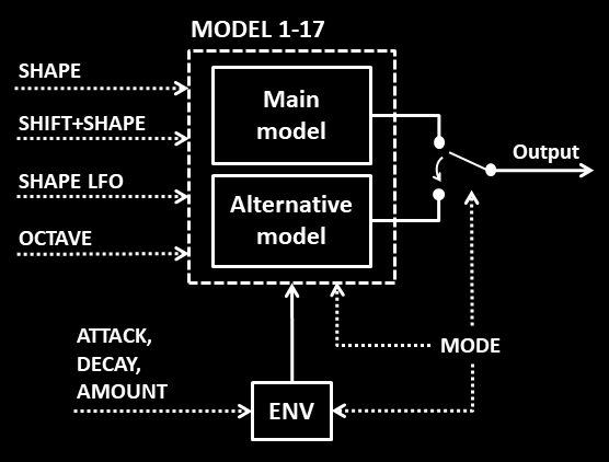
PAR1: MODEL [1…17]
Selects one out of 17 models, or better model pairs. The choice between the main and alternative model is handled with the MODE parameter. The model description is given in a separate section below.
PAR2: OCTAVE [1…3]
Selects the octave of the oscillator, which can be transposed either two octaves below the given pitch (OCTAVE=1), one octave below (OCTAVE=2) or at the same pitch (OCTAVE=3). However, for some models, different definitions apply.
PAR3: MODE [1…98]
The MODE value is treated as two separate digits, which control different things.
The left digit sets the number of adjacent models which can also be randomly picked for the next key, starting from MODEL+1. If the chosen index exceeds 17, the system uses wrap-around logic to start over at index 1, etc. If the left digit is 0 (not shown in the screen), random selection is disabled.
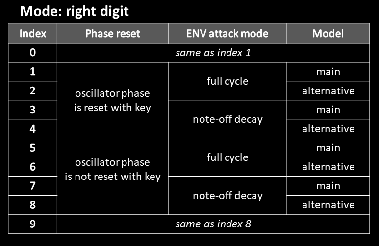
The right digit controls three different settings, as defined in the table below. The most important function is switching between the main and alternative models. As shown in the table, only 8 out of the 10 possible choices (0-9) are distinguished.
PAR4: ATTACK [0…100%]
Sets the attack time of the A/D-envelope.
PAR5: DECAY [0…100%]
Sets the decay time of the A/D-envelope.
PAR6: AMOUNT [-100%…100%]
Sets the envelope amount, which can have positive or negative values.
Note: for attack=0, decay=0, the envelope is deactivated.
SUB: OSC models
This section describes the implemented main and alternative oscillator models, which represent different types of waveforms. These shall be abbreviated as MAIN and ALT. The waveforms are altered in various ways, mainly using SHAPE, but may also depend on SHIFT+SHAPE or OCTAVE. The envelope is abbreviated as ENV.
Octave settings
Some models do not use the standard definition of the OCTAVE parameter with three identical timbres in different octaves. This is done to achieve more variety in the generated sound. If the model deviates from the standard case, often a table is provided to give the user an idea of the arrangement. For many models there are two oscillators involved which are always locked in phase. It is good to remember that for each OCTAVE setting, always the oscillator with the lower octave position – which can have the values -2 (two octaves down), -1 (one octave down) or 0 (main pitch) – defines the pitch of the final sound.
Default configuration
It is convenient to introduce a default configuration, allowing the models to be described in a much more compact way. The following points, which are used most often, apply to a model unless otherwise specified:
By default, …
- SHAPE is the only parameter to shape the original waveform.
- SHIFT+SHAPE is used to apply a mild lowpass on the original waveform.
- SHAPE LFO and the envelope (ENV) both modulate SHAPE.
- the main model (MAIN) is gain-compensated for SHAPE.
- the alternative model (ALT) is just the gain-uncompensated version of the main model.
- the OCTAVE-parameter yields three waveforms of the same timbre, just in different octaves.
Model 1: clipped triangle-wave
The triangle-wave is widely used as an added sub-oscillator, along with the square wave. However, in combination with other main oscillators such as sawtooth or pulse, the triangle wave often sounds too mellow to be clearly recognized or must be relatively loud, requiring a large amount of headroom. Boosting and clipping the triangle wave adds harmonics without using additional headroom. Such a signal can be better heard on small speaker systems and, not to forget, sounds different. The more you crank up SHAPE, the more the triangle turns into a square, but without the prominent high frequencies. For SHAPE=0%, no clipping is applied.
Tip: A positive envelope can add a nice initial punch to an otherwise pure triangle wave.
Model 2: phase-shifted triangle waves
In this model, a similar waveform is obtained using MAIN (= main waveform), just with a different technique. Two identical triangle waves are phase-shifted against each other. The phase shift is controlled by SHAPE. With active modulation, this method sounds different compared to model 1. SHIFT+SHAPE applies a mild lowpass filter (standard behavior).
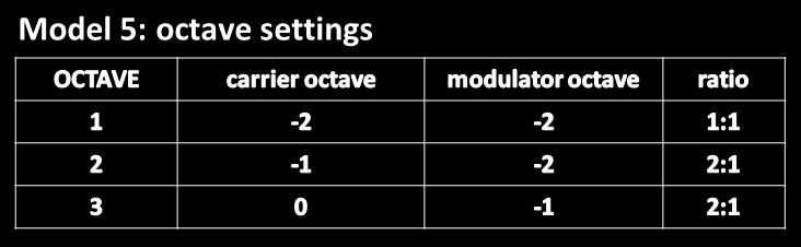
For ALT (= alternative waveform), the two triangle waves are generated the same way, but can also be phase-modulated by a square wave. The modulation intensity is determined by SHIFT+SHAPE and ENV (=envelope). OCTAVE works differently for carrier (the triangle waves) and modulator, similar to model 5.
Model 3: linear FM, absolute, ratio 1:2
In this model, a carrier is modulated by a sine wave using linear FM (through-zero). For MAIN, the carrier is a triangle wave, for ALT a sine wave. The frequency ratio is 1:2 (carrier:modulator) and SHAPE sets the modulation amount. SHIFT+SHAPE adjusts the (initial) phase shift between the carrier and modulator and has a very subtle effect, unless SHIFT+SHAPE is tweaked during the decay of the sound or using the motion sequencer (XD). The FM modulation is strongest for low frequencies and declines for higher frequencies, because the maximum frequency deviation is absolute, i.e. independent of the carrier frequency.
Model 4: linear FM , absolute, ratio 1:3
This model is similar, but uses a ratio of 1:3. SHIFT+SHAPE adjusts the standard lowpass filter instead of a phase shift.
Model 5: linear FM, relative, variable ratio
This model performs another form of through-zero linear FM where the created timbre is independent of pitch, because the maximum frequency deviation is proportional to the carrier frequency. A sine carrier is modulated by a sine. The octave position (pitch) of the modulated carrier and the ratio depend on OCTAVE as shown below. The resulting pitch is equal to the modulator pitch as it is either lower or equal to the carrier.
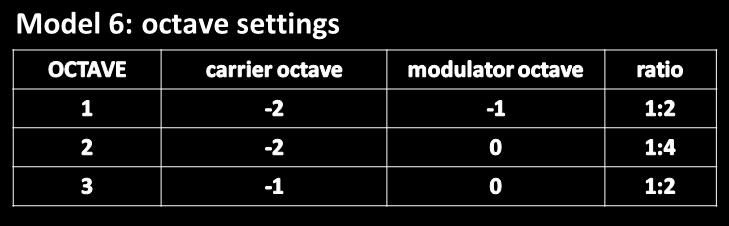
Model 6-7: PM using triangle modulator
In model 6, a carrier is phase-modulated by a triangle wave, controlled by SHAPE. For MAIN, the carrier is a triangle, for ALT a sine. SHIFT+SHAPE applies a phase shift between carrier and modulator. The octave settings are given below. The resulting pitch is equal to the carrier pitch as it is either lower or equal to the modulator.
In model 7, for MAIN we have the same arrangement as before, but the SHAPE LFO modulates the phase shift between the carrier and modulator. For ALT, a triangle carrier is also used, but the SHAPE LFO signal is bent in a way that a fullscale LFO triangle wave becomes a perfect sine wave, preventing an audible two-frequency toggling of the affected modulator, which happens for MAIN.
Model 8: dynamic waveform mixing (triangle, square)
MAIN is a mix of a triangle wave and a square wave. SHAPE controls the fading while SHIFT+SHAPE applies a phase shift between these waveforms. When SHIFT+SHAPE is 100%, the waves are out of phase and produce a characteristic sound without the lowend when SHAPE is around 50%.
ALT uses a different arrangement with three square waves in different octaves, W1-W3. W1 plays two octaves lower, W2 one octave lower and W3 at the main pitch. SHAPE and SHIFT+SHAPE are used to mix the squares in any proportion. OCTAVE defines which of the waves are mixed first, using SHAPE. These are the ones for which the fading can be modulated. The role of SHAPE and SHIFT+SHAPE for MAIN and ALT is shown below. As usual, the SHAPE LFO and the ENV modulate SHAPE.
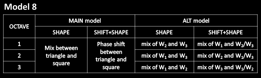
NOTE: For ALT, you won’t hear any effect of SHAPE as long as SHIFT+SHAPE remains at 0%, since the “cross-fader” is fully set to the third waveform, and not to the mix between the other waveforms. For example, for OCTAVE=1 this would be W1.
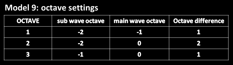
Model 9: ring-mod between folded triangle wave and sub wave
The generated timbre arises from a ring-modulation of a folded triangle wave and a lower-pitched sub wave . SHAPE adjusts the folding. As expected, the pitch of the ring modulator output is equal to the sub wave pitch.
For MAIN, the sub wave is a square. As usual, SHAPE LFO and ENV modulate SHAPE while SHIFT+SHAPE controls a mild lowpass.
For ALT, the sub wave is a boosted and clipped triangle whose gain factor is controlled by SHIFT+SHAPE. The SHAPE LFO creates an oscillating phase shift between the triangle wave and the sub wave. The OCTAVE settings are given below. Equal octave difference for case 1 and 3 results in the same type of timbre while case 2 sounds different.
Model 10-11: sub wave, AM-modulated by a pulse wave
Model 10 uses a sub wave which is AM-modulated by a main wave. The octave arrangement is the same as for model 9. For MAIN, the sub wave is a triangle, for ALT a sine wave. SHAPE controls the positive width of the pulse wave while SHIFT+SHAPE defines the amount of amplitude modulation (AM). For SHIFT+SHAPE=0%, the AM modulation is highest, resulting in a ring-modulation. For increasing values of SHIFT+SHAPE, the AM modulation is progressively reduced leading to a mellower sound.
Model 11 works similar, but uses a different phase offset between the sub wave and the pulse wave.
Model 12: two square-waves, phase-shifted relative to each other
This waveform is similar to one model included in TONE, but provides gain compensation for MAIN.
Model 13: classic pulse wave, centered PWM
MAIN consists of a DC-free pulse wave created with two phase-shifted sawtooths, gain-compensated. The pulse width changes around a static center of the pulse. ALT is a standard pulse wave, not DC-free, without gain compensation, but also using centered PWM.
Model 14: square wave, FM-modulated by a triangle
This simple model replaces direct pulse-width modulation with frequency modulation to achieve a similar effect, using a triangle modulator and a square wave carrier. The octave settings are the same as for model 5.
Model 15: ternary pulse wave, FM-modulated by a triangle
This model is a variation of the previous one, using a ternary pulse wave instead of a standard square as the carrier.
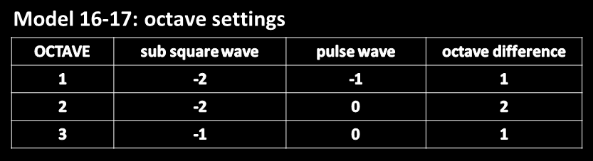
Model 16-17: Sub square wave, AM-modulated by variable pulse wave
For model 16, a sub square wave is AM-modulated by a pulse wave with variable width, which is controlled by SHAPE. The modulation is set by SHIFT+SHAPE. For SHIFT+SHAPE=0%, full modulation is applied, resulting in a ring-modulation. For higher values the AM-modulation is reduced, sounding more mellow.
Model 17 is essentially the same, but uses a different phase shift between main and sub wave.
CRUDE uses lo-fi effects on a selected oscillator model to obtain interesting sound textures. You can choose between 20 different basic oscillator models which all have just one waveform parameter SHAPE. The available effects are rate reduction using sample-hold, bit crushing, slew-rate limitation, saturation and clipping. Two different topologies are offered, which determine the order of the signal manipulators. The sample-hold effect, when heavily applied, will ultimately destroy the tuning in the upper octaves, which can be useful to create certain sound effects or percussive sounds. The SHAPE LFO can be used as usual to modulate the basic waveforms. In combination with the bit crusher, rich and complex tones can be generated. In contrast to the other oscillators, CRUDE disregards aliasing performance of the effects to abandon any restrictions on waveform manipulation.
For topology 2, the saturator comes before the quantizer (bit crusher). In this way, the effect of the quantizer can be fine-tuned. On the other hand, the signal cannot be independently saturated as in topology 1. Another difference is a change in the quantization curve.
CRUDE: operation and controls
SHAPE
Adjusts the model-depend shape of the waveform.
SHIFT+SHAPE
Sets the degree of tuning variation across voices.
SHAPE LFO
Modulates the model-dependent shape of the waveform.
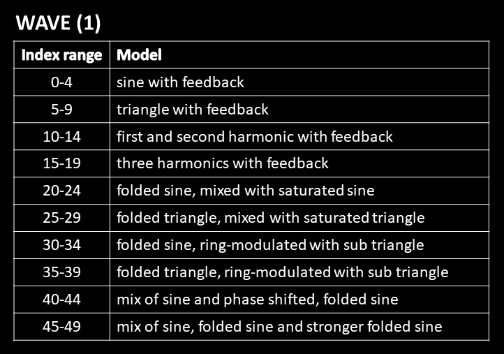
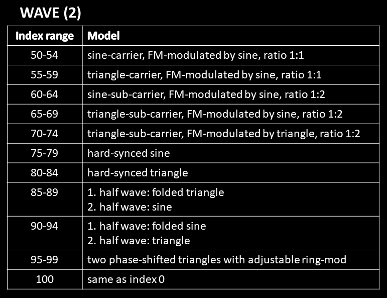
PAR1: WAVE [-100%…100%]
The WAVE parameter requires a clear explanation. First, the percentage mode (%) is used solely to enable access to negative values. The bipolar usage of this parameter effectively doubles the number of available values, meaning that the percentage symbol itself should be disregarded in interpretation.
- In principle, the WAVE parameter selects the topology, the basic oscillator model and the degree of quantization applied on the waveform of the model.
- Each oscillator model is associated with five adjacent indices, representing different quantization settings. The lowest index corresponds to no quantization, while the highest index represents maximum quantization, corresponding to the lowest bit depth.
- Negative WAVE values refer to the same model and quantizer setting as their positive counterparts (absolute values), but use topology 2, whereas positive values use topology 1.
The first model for topology 1 occupies indices 0…4, where index 0 stands for no quantization and index 4 represents maximum quantization. The corresponding mirrored model for topology 2 uses only the indices -1…-4, leaving out the unquantized mode which would also occupy index 0. The second model uses indices 5 to 9, with its mirrored counterpart using -5 to -9, and so on.
The list of the models is given below. It is sufficient to consider only the positive part (topology 1), since the negative part is just mirrored. For the FM modes (which are actually PM), ratio is defined as carrier:modulator.
PAR2: DECIMATE [0…100%]
Adjusts the degree of decimation using sample-and-hold logic. This effect introduces aliasing, resulting in atonal sound content mixed with the waveform. At higher settings, the original pitch may disappear entirely. At 0%, no decimation occurs.
PAR3: SLEW LIM [0…100%]
Sets the degree of slew rate limitation. In this context, the slew rate defines the maximum signal change from sample to sample. For higher parameter values, this rate is gradually reduced. The effect is non-linear but sounds much like a lowpass. It models early-age analog OPAMPS where the maximum slope of the output voltage is limited due to circuit limitations. For a value of 0%, no slew rate limitation occurs.
PAR4: SATURATE [0…100%]
Adjusts the amount of saturation. At 0%, the signal lies in the linear region.
PAR5: CLIP [0…100%]
Sets the amount of clipping gain. At 0%, no clipping occurs.
PAR6: HIGHPASS [0…100%]
Adjusts the amount of highpass filtering. Such filtering can be desirable to suppress low-frequent artefacts. Also, if there is a DC component present in the signal, this component can be removed and this will influence the limiter. For a value of 0%, no highpass filtering occurs.
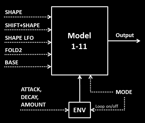
The double-fold oscillator DBFOLD explores different oscillator constellations where basic waveforms such as sine or triangle can be folded once or twice, realized in eleven different models. The folded result can be mixed back with the unprocessed waveform or another base tone. For some of the models, one folding operation is replaced with FM. An essential part of the waveform shaping is a built-in saturator or clipper to make the sound stand out better. For modulation, the oscillator incorporates a linear envelope (ENV), which can be optionally looped. Combined with the SHAPE LFO, interesting sound structures can be realized. Four modulation modes exist with different assignments for ENV and SHAPE LFO. The selection of the oscillator model and envelope mode is handled with one single parameter mode.
DBFOLD: controls
SHAPE
SHAPE controls either the first folding of an initial waveform or the FM-modulation intensity applied on such a waveform.
SHIFT+SHAPE
SHIFT-SHAPE adjusts the amount of clipping or saturation, depending on the model. In one case, though, SHIFT-SHAPE controls a third folding.
SHAPE LFO
Can be used to either modulate the first or second transformation (folding), depending on the modulation setting.
PAR1: FOLD2 [0…100%]
Adjusts the degree of the second folding of a waveform.
PAR2: BASE [0…100%]
Adjusts the mix between the folded waveform and the original waveform or some other base tone. For some ring-modulation models, though, BASE adjusts the phase offset of the base tone.
PAR3: MODE [1…101]
Selects the oscillator model with the left digit and the envelope mode with the right digit. In the first table below, x stands for any left digit (or for “10” for index 101). For modes 2 and 7, the LFO is inverted. For modes 5 and 10, the LFO amount is modulated by the envelope.
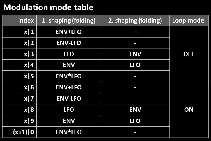
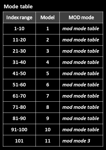
In the second table above we see the mapping of the MODE parameter. The modulation mode table is repeated 10 times, each time for a different oscillator model. This means that index range 1-10, 11-20, 21-30, and so forth correspond to the modulation mode table. For model 11, though, we only have one index 101. For this model, envelope mode 3 applies. The actual model descriptions are found here.
PAR4: ATTACK [0…100%]
Sets the rise time of the linear A/D-envelope.
PAR5: DECAY [0…100%]
Sets the fall time of the linear A/D-envelope.
PAR6: AMOUNT [-100%…100%]
Sets the envelope amount, which can have positive or negative values.
Note: for attack=0, decay=0, the envelope is deactivated.
DBFOLD: model description
Model 1
A sine wave is double-folded using sinusoidal wave-folders (SHAPE, FOLD2). The resulting wave is mixed with a base tone (BASE) and finally clipped (SHIFT+SHAPE).
Model 2
A sine wave is double-folded using sinusoidal wave-folders. The resulting wave is first clipped and then mixed with a base tone.
Model 3
A sine wave is double-folded using triangular wave-folders. The resulting wave is mixed with a base tone and finally clipped.
Model 4
A sine wave is double-folded using triangular wave-folders. The resulting wave is first clipped and then mixed with a base tone.
For this model, the modulation range of both folds is extended to negative values by simple mirroring the positive range. Negative values can only be reached through modulators (ENV, LFO).
Model 5
A triangle wave is double-folded using triangular wave-folders. The resulting wave is mixed with a base tone and then saturated.
The modulation range for the second folding is extended to negative values.
Model 6
A triangle wave is first folded with a triangular and then with a sinusoidal wave-folder. The result is first saturated and then mixed with a triangle base tone.
Model 7
An octave-shifted triangle wave is folded with a triangular wave-folder (SHAPE). In parallel, a sine wave, which is regarded as the base tone, is folded using a sinusoidal wave-folder (FOLD2).
The ring-modulation product of these waves is finally clipped (SHIFT+SHAPE).
The BASE parameter controls the phase offset of the sinusoidal base tone relative to the main triangle wave (BASE).
Model 8
An octave-shifted triangle wave is folded with a triangular wave-folder. In parallel, a sine wave, which is regarded as the base tone, is folded using a sinusoidal wave-folder. The BASE parameter controls the phase offset of this base tone.
The ring-modulation product of these waves feeds another triangular wave-folder (SHIFT+SHAPE).
Model 9
An octave-shifted sine wave is folded by a sinusoidal wave-folder (FOLD2). The produced wave is used to perform FM-modulation of a sinusoidal carrier (SHAPE). The result is mixed with a triangle base tone (BASE) and finally saturated (SHIFT+SHAPE).
Model 10
An octave-shifted sine wave is folded by a sinusoidal wave-folder. The produced wave is used to perform FM-modulation of a triangle carrier. The result is mixed with a triangle base tone and finally saturated.
Model 11
This model is similar to 10, but uses a phase-shifted triangle base tone.
One-trick pony oscillators
The next oscillators have a somewhat smaller range of sound, but can do one “trick” quite well. Nevertheless, these oscillators can surprise for certain settings. The simplicity of their controls is a benefit. An oscillator like FIVE could also have been included in this group.
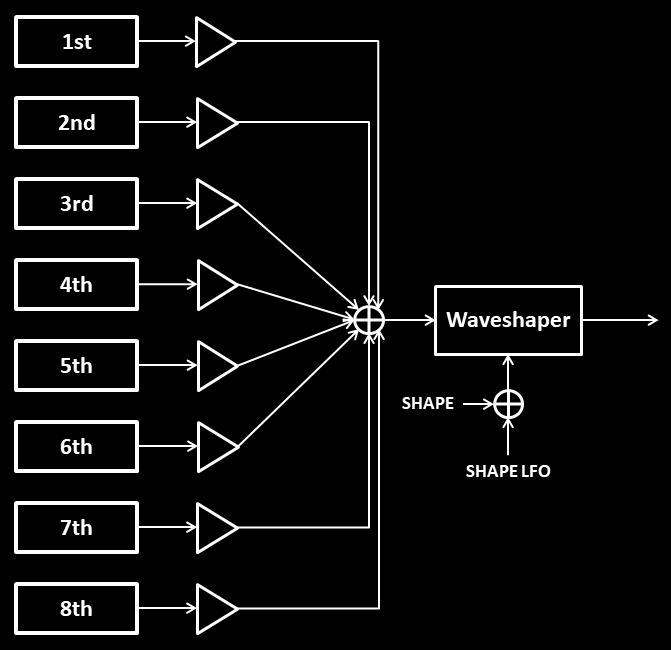
HARMON is a straightforward oscillator that utilizes a form of rudimentary additive synthesis. The signal is constructed using only the first eight harmonics. The amplitudes and polarities of harmonics 2–7 are determined by the menu parameters 1–6, while the 8th harmonic is defined by SHIFT-SHAPE. One convenient feature is that the signal is automatically normalized to preserve consistent headroom. When you increase the amplitude of a harmonic by adjusting its parameter, all other harmonics, including the fundamental, are (slightly) decreased. The first harmonic, which is called the fundamental, does not require any adjustment and has a fixed amplitude of 1 (100%), before normalization.
As expected, the resulting signal is rather dull in the lower octaves. Real additive synthesizers require 256 harmonics or more to fill the whole audio spectrum for all notes, also very low ones. To optionally enrich and brighten the sound, the signal is fed into a sinusoidal waveshaper, which generates additional overtones. This waveshaper is an essential part of the oscillator and is controlled by SHAPE and SHAPE LFO.
Since bipolar parameters are used, the default signal has the amplitudes of the harmonics 2-7 set to -100%. It is, thererfore, recommended to reset the amplitudes to 0 before starting to tweak the patch, as described in the tech notes.
When you crank up SHAPE and use a strong harmonic setting, the oscillator wave can become quite harsh in the upper octaves, being brighter than the analog VCOs. You can use the filter to reduce the spectrum in the usual way. Additionally, the filter envelope can be utilized to obtain a sharp attack if desired.
HARMON: controls
SHAPE
Adjusts the input gain of the signal going into the waveshaper and, therefore, adjusts its impact. When set hard left, the waveshaper has no audible effect.
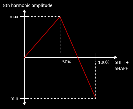
SHIFT+SHAPE
Sets the amplitude and polarity of the 8th harmonic according to the following mapping. Up to 50% the positive amplitude rises to its maximum. For higher values, it decreases back to zero and eventually reaches its most negative value. In this way, the default value is 0.
SHAPE LFO
Modulates the waveshaper impact (input gain).
PAR1-PAR6 [-100%…100%]
Adjusts amplitude and polarity of harmonics 2-7. For negative values, the amplitude is inverted. The polarity has an effect as soon as the waveshaper comes into play.

A well-known technique for obtaining a sawtooth from a sine or triangle wave is to apply phase modulation (PM) feedback. For CHAOS, this scheme has been extended in order to (hopefully) obtain other, more complex waveforms. The extension is done in two ways.
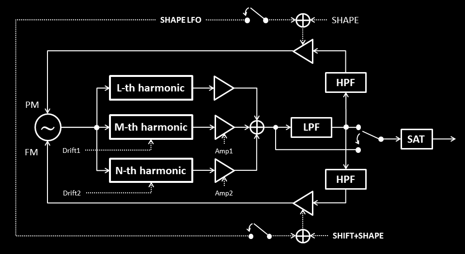
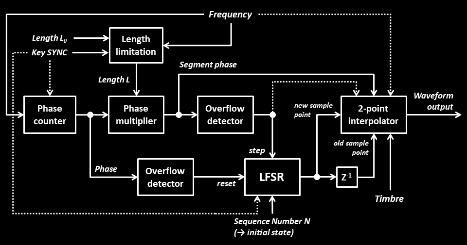
First, the oscillator uses feedback applied to a basic three-component waveform in order to attain a signal with a full overtone spectrum, shown in the Figure below. The original waveform can consist of either three partials (sine waves) or three triangle waves at partial frequencies. These components are locked in phase, but the upper two (M and N) can start to drift if activated. Second, the PM feedback can be accompanied by FM feedback.
For the PM/FM-scheme to work and deliver low-artefact waveforms which stay in tune, an adjustable lowpass and a fixed highpass filter is inserted in the feedback path. The user must manually set the cutoff frequency of the lowpass. The required cutoff value to achieve a signal perceived as clean depends on the selected component amplitudes and frequencies, but also the highest played note, and is difficult to derive automatically. Such automation might not even be desirable, as it would prevent the user from deliberately introducing a lo-fi character into the waveform.
The output signal is slightly saturated to ensure a more consistent loudness. The L-th harmonic always has a full level or is muted, see frequency table.
CHAOS: controls
SHAPE
Adjusts the amount of phase modulation (PM) in the feedback path.
SHIFT+SHAPE
Adjusts the amount of frequency modulation (FM) in the feedback path.
SHAPE LFO
Depending on mode, the SHAPE LFO modulates the PM amount, the FM amount, or both.
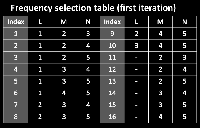
PAR1: Mode
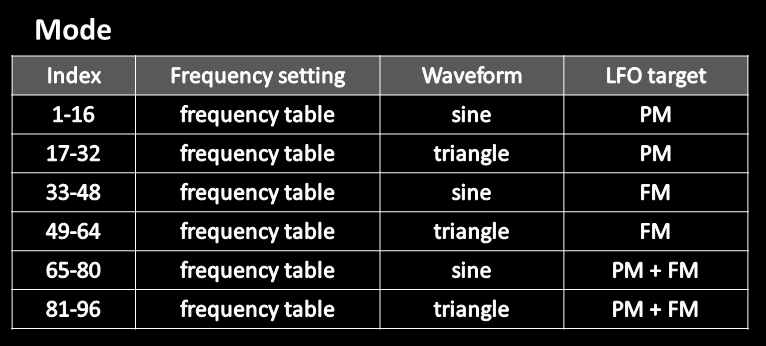
First, we introduce the frequency selection table. As shown, the L-th harmonic is mostly the fundamental, but can also be an overtone and is even muted for the highest-indexed modes 11-16. The frequency table is repeated six times, each time with a different choice for the used waveform and LFO target, resulting in 96 different modes. In practice, mode selection can be done by ear rather than looking at these tables.
PAR2: Amp1 [-100%…100%]
Sets the amplitude and the polarity of the M-th harmonic.
PAR3: Amp2 [-100%…100%]
Sets the amplitude and the polarity of the N-th harmonic.
PAR4: Drift1 [0…100%]
Adjusts the drift for the M-th harmonic.
PAR5: Drift2 [0…100%]
Adjusts the drift for the N-th harmonic.
PAR6: Lowpass [-100%…100%]
Sets the cutoff frequency and also switches between lowpass mode and direct mode. For positive values, the lowpass-filtered wave is used as the signal into the output saturator. For negative values, the wave is taken directly, while the lowpass filter is applied only in the feedback path. The lowest cutoff frequency (highest impact of the filter) is given at +-100%. Up to a certain point, lower cutoff frequencies improve loop stability.
Sequence oscillators
The sequence oscillator is a new type which can create more complex waveforms without having to store them as sample data. Just like in FM synthesis, all waveforms are calculated in real time. The basic scheme of the oscillator model is shown below.
The task of a static oscillator is to produce a periodic wave with a desired static single-cycle waveform, defining the timbre. This task can be divided into two subtasks, namely to establish an oscillation signal and to calculate a waveform based on this signal. In a digital system, the oscillation can easily be realized with a phase counter. For each sample in time, this counter is incremented by a value representing the current frequency, and overflows after every cycle period. The rest of the oscillator unit has to calculate the desired output waveform, taking the sawtooth-like phase counter values as an input.
The sequence oscillator – as a special type of a waveform calculation scheme – splits the single-cycle period into L segments of equal length. Within each segment, a two-point interpolator is responsible for calculating the waveform between two given samples A and B which represent the edges of the segment and can only have the bipolar values +1 or -1. The interpolated waveform in the segment depends only on these two samples and no other.
A phase multiplier takes “Length L” as an input parameter and generates a segment phase from the output of the phase counter, denoted as the main phase. This segment phase rotates L times as fast as the main phase and determines the position within a segment for the interpolator. The resulting waveform is shown in Figure 2 for a length-2 and an exemplary length-8 sequence.
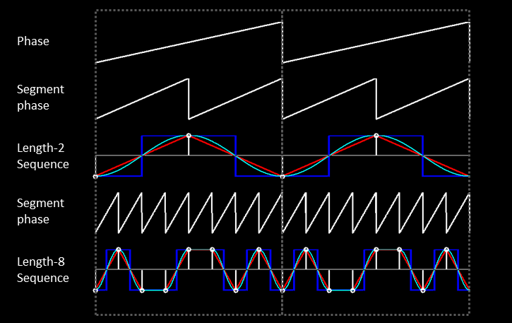
The whole scheme can be vierwed as a possible extension of basic waveforms. In the Figure above, sine, triangle and square are reinterpreted as sequences “(1) (-1)” of length L=2, that is as alternating sample transitions with their characteristic shape. The length-8 sequence delivers a different timbre using the same basic waveform transitions. On average, with rising sequence length, the harmonic content increases while the fundamental decreases, resulting in a brighter timbre. Hence, a filter is often essential to balance the final sound.
A linear feedback shift register (LFSR) in Figure 1 is used to generate the bipolar sample sequence. Alternatively, a simple shift register could be used instead of the LFSR, storing the whole binary sequence. Normally, such an LFSR is used to create long pseudo-noise sequences and, therefore, to imitate noise. In this scheme, though, the LFSR is restarted after L segments, ensuring the tonality of the signal.
After every overflow of the segment phase, the LFSR is stepped one position further, providing the next bit (bipolar sample), while the previous sample is kept with a delay-element, as it is still required for the interpolator.
After every overflow of the main phase, the LFSR is restarted by loading its initial state, as mentioned before.
In general, the user has three parameters to select a specific waveform by
- selecting a sequence number representing the LFSR initial state
- selecting the (desired) length of the sequence
- selecting the interpolation function
Note: different sequences will diverge only after a certain common length. This length varies for different sequence pairs.
In the implementation, the interpolation function depends on the pitch for many transition types. Aliasing is mitigated by avoiding sharp transitions with rising pitch, gradually changing the transition function applied in the interpolator.
In addition, the sequence is restricted in its length in relation to the pitch. For higher notes, the maximum allowed sequence is shortened. This decision is made when a key for a voice is striked, provided that portamento is off. Length limitation is also done for low frequencies to avoid any rattling. Therefore, the applied sequence length L may be shorter than the “desired” length L0 that the user actually selects in the menu. This effective length L must be at least equal to 2 to ensure a bit flip, and therefore an oscillation. For this reason, all sequences start with the pattern “(1) (-1) …”, corresponding to the binary sequence “10…”. As these sequences are shortened up to the mimimum of L=2, an oscillation is always maintained.
The sequence oscillator collection consists of six oscillator models.
- SEQ provides two sequence oscillators with variable timbre, sequence number and length. These can be mixed in any ratio, but also ring-modulated or de-tuned against each other.
- SEQ2 can be seen as a simplified version of SEQ, with the addition of an envelope and extended mixing options.
- SEQ3 uses a sine/triangle sequence oscillator as a phase-modulator of a sine/triangle carrier.
- SEQ4 introduces pulse width modulation (PWM) for sequences. The waveform is synthesized as a combination of a PWM-capable sequence and a bass tone which provides a solid fundamental.
- SEQ5 passes a pulse sequence through a resonant 12-dB or 24-dB lowpass filter with variable key tracking and drive.
- SEQ6 combines sequencing with linear FM, for which a sequence can be used as a modulator or carrier. The oscillator also includes some non-sequence linear FM modes.
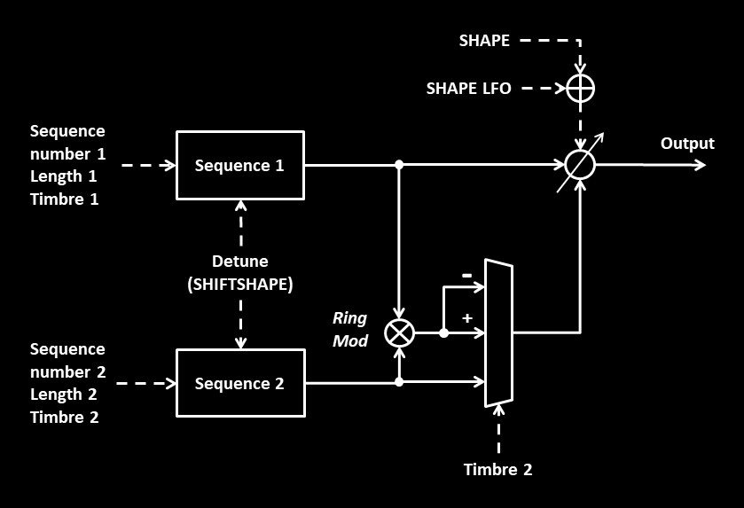
SEQ follows the original concept in a straight forward way, providing two parallel sequence oscillators which are characterized by sequence number, length and the used interpolation function called timbre. Nine of such timbres are available, ordered with increasing harmonic content. The output of the second oscillator can be replaced by the ring modulation product of the two oscillator waves, either with positive or negative polarity. Each oscillator can play in the main or sub octave, and oscillator 1 can also play one fifth above.
The two waves can be mixed in any ratio using SHAPE. When ring modulation replaces wave 2, SHAPE effectively determines the amount of amplitude modulation (AM) applied to wave 1, either with positive or negative polarity. For intermediate SHAPE settings, one polarity will sometimes sound fuller than the other.
SHIFTSHAPE can be used to detune the two oscillators. For SHIFTSHAPE=0, oscillators are locked and merge into one. Finally, some randomness can be introduced by allowing the sequence length to vary between L, L+1 and L+2.
SEQ: controls
SHAPE
Mixes between oscillator wave 1 and 2, or between wave 1 and the ring modulation of wave 1 / wave 2 if ringmod is selected. In the second case, SHAPE effectively determines the amount of AM modulation of wave 2 applied to wave 1.
SHIFTSHAPE
Adjusts the amount of detuning between oscillator 1 and 2. For SHIFTSHAPE=0, oscillators are locked.
SHAPE LFO
Modulates the SHAPE setting, i.e. the mix between the waves (standard behavior).
The following menu parameters are applied with every new key strike and not immediately. This means that active voices and voices fading out are not affected until they are retriggered.
PAR1: Seq 1 [1-64]
For 1-32, chooses between 32 different sequences for the first oscillator, defined by the initial state of its feedback shift register. The numbers 33-64 select the same sequences, but without applying length limitation for very low pitch.
Note that the waves produced by different sequences of equal length differ only after a certain minimum length.
PAR2: Length 1 [1-96]
For values 1-32, this parameter sets the desired length of the first oscillator sequence between L=2 and L=33.
For values 33-64, L is again set between 2 and 33, but the length is randomly chosen between L and L+1.
For values 65-96, the desired sequence length is chosen between L, L+1 and L+2.
For all three cases, additional length limitation applies, as described in the introduction.
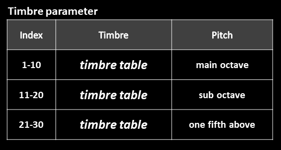
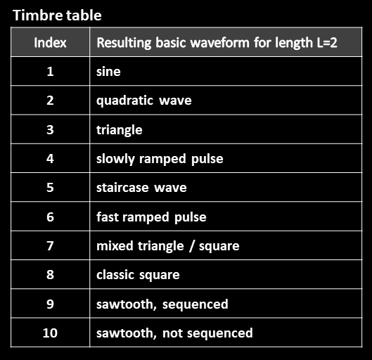
PAR3: Timbre 1 [1-30]
Selects the interpolation function defining the “timbre” for the first sequence, according to the following two tables. The 10 different selectable timbres are repeated three times, each time for a different pitch setting. The brightness increases from timbre 1 to 8. Timbre 10 is just a filler mode.
PAR4: Seq 2 [1-64]
Selects the sequence number for oscillator 2 in the same manner as PAR1.
PAR5: Length 2 [1-96]
Selects the sequence length for oscillator 2 in the same manner as PAR2.
PAR6: Timbre 2 [1-60]
Selects the timbre and pitch for the second sequence and also optionally enables ring modulation with normal or inverted polarity, according to the following table. The basic timbre table is the same as used for sequence 1.
SEQ2 is a stripped-down version of SEQ omitting a few features but offering an envelope to be able to change the mix of the two sequences during an initial transition. The feedback shift-register (LFSR) used is simpler and offers only 8 different sequences, given that all of these must start with (1),(-1). With this approach, both the sequence number and the length can be stored in a table, and the user simply selects one out of 101 sequences. Hence, the number of combinations – but also the maximum sequence length – is considerably smaller than for SEQ, but still very useful. The table is arranged such that no sequence appears twice. As the user turns up the sequence parameter, each time the length is incremented only after all different sequences for this length have been cycled through.
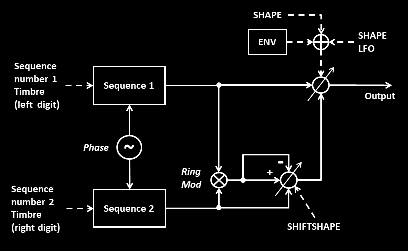
With no detuning possibility, the two sequence generators share the same phase and are in fact just parts of one complex oscillator, represented by the entire signal flow as shown above.
SEQ2 puts more focus on AM modulation. SHAPE and SHIFTSHAPE are used to mix between wave 1, wave 2 and the ring-modulation product between them, being more flexible than SEQ with its switching.
SEQ2: controls
As previously described, compared to SEQ, only one parameter per sequence is used to select both the sequence and its length. In addition, a few interpolation modes have been dropped to allow all timbre combinations to be selected with just one parameter. In return, the user can adjust and use the additional envelope.
SHAPE
SHAPE mixes between sequence 1 and a mix of sequence 2 and the ring modulation product, adjusted by SHIFTSHAPE.
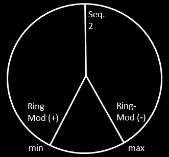
SHIFTSHAPE
Mixes between sequence 2 and the ring modulation product with positive or inverted sign, according to the following diagram. In the middle position, the original sequence wave resides. Moving SHIFTSHAPE to the left adds positive ring-modulation, to the right adds negative ring-modulation.
Note: Since the default setting for SHIFTSHAPE is usually 0, the oscillator starts with ring mod (+) fully enabled.
SHAPE LFO
Modulates the SHAPE setting, i.e. the mix between the waves (standard behavior).
PAR1: SEQ1 [1-101]
Selects one out of 101 sequences with given initial state and length for wave 1.
PAR2: SEQ2 [1-101]
Selects one out of 101 sequences with given initial state and length for wave 2.
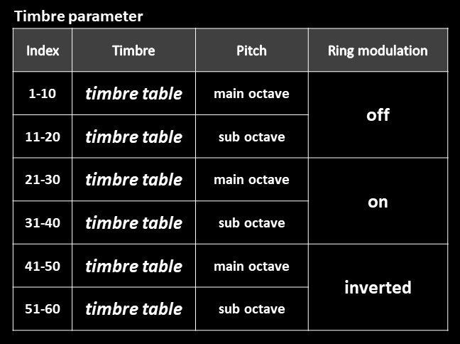
PAR3: TIMBRE [0-99(%)]
The “%”-suffix merely ensures that the TIMBRE-parameter starts from 0 and not 1 and can be ignored.
The interpolation function of each sequence, called timbre, is selected using just one menu parameter for both sequences. The left digit adjusts the timbre for sequence 1, the right for sequence 2. For each sequence, the user can select one out of five different timbres as well as the octave, resulting in 10 different settings, which are defined in the following table.
PAR4: ATTACK [0…100%]
Sets the attack time of the A/D-envelope.
PAR5: DECAY [0…100%]
Sets the decay time of the A/D-envelope.
PAR6: AMOUNT [-100%…100%]
Sets the envelope amount, which can have positive or negative values.
Note: for attack=0, decay=0, the envelope is deactivated.

SEQ3 deals with digital phase modulation (PM), which traditionally has been called ‘FM’. In this implementation, a simple carrier is modulated by a sequence, allowing more complex sounds to be generated than with two basic waveforms. The carrier and the sequence can be of type sine or triangle, resulting in four selectable combinations. Carrier and modulator are always locked in phase, and their frequency ratio is covered with the RATIO parameter. SHAPE, SHAPE LFO and the built-in envelope modify the modulation amount. SHIFTSHAPE can be used to mix the sequence directly into the output. To avoid excessive brightness and potential aliasing, the PM modulation amount is automatically lowered or limited when either the sequence length, ratio or voice pitch are increased. Each of these cutbacks can be disabled or reduced, changing the character of the oscillator.
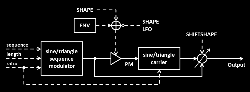
SEQ3: controls
To distinguish different modes, the first three parameters are functionally “overloaded” as usual to include switching.
PAR1: SEQUENCE [1-96]
Selects the sequence and also determines the note on the keyboard from which PM modulation is progressively reduced for higher notes. Values 1-32 select all of the sequences while maintaining the lowest note for modulation reduction, leading to the most mellow sound. Values 33-64 select the same sequences, but use a moderate note position. Values 65-96 use the highest note setting for an overall brighter sound in the upper registers.
PAR2: LENGTH [1-80]
Determines the length of the sequence, the type of carrier, and whether a higher length shall progressively limit the maximum modulation amount.
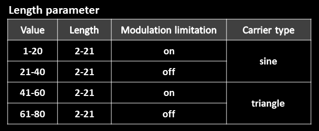
PAR3: RATIO [1-90]
The RATIO parameter defines the carrier-modulator frequency ratio (CM), the behavior regarding PM limitation and the sequence type. For a CM-ratio of 1:2, 2:1 or 1:1, it was found that a phase offset between carrier and modulator has a significant impact on the sound. For these CM-ratios, the RATIO parameter also distinguishes between different phase offsets. The ratio table shown left is repeated three times, each time for a different setting regarding PM limitation and sequence type.
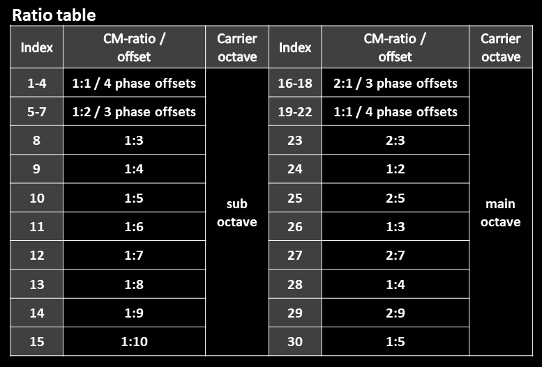
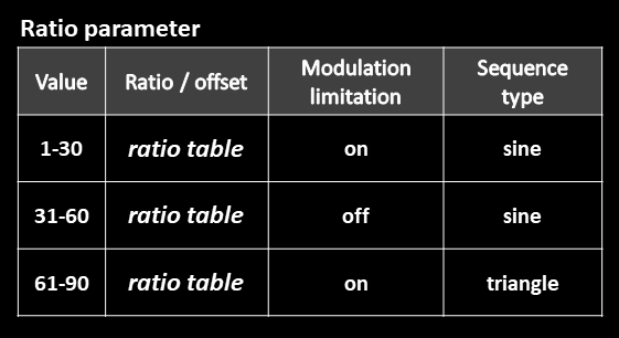
PAR4: ATTACK [0…100%]
Sets the attack time of the A/D-envelope.
PAR5: DECAY [0…100%]
Sets the decay time of the A/D-envelope.
PAR6: AMOUNT [-100%…100%]
Sets the envelope amount, which can have positive or negative values.
Note: for attack=0, decay=0, the envelope is deactivated.

SEQ4 introduces the pulse sequence with variable pulse width, which can be modulated via PWM. It also follows the idea to create a waveform from two components, namely a sequence with possibly long length and high degree of brightness, and a base tone, which provides a solid fundamental and which will be called bass tone hereafter. The right balance between these components often results in a good sounding timbre.
In addition, the user can compensate an overly bright sequence with the warmth-control, which is a simple low-shelf. This shelf helps the main synth filter to achieve its goal, especially when the bass tone is absent.
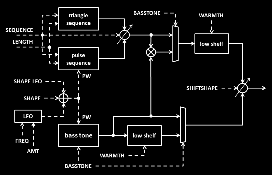
For the timbre of the sequence, the user can choose between a pulse, an equal mix of pulse and triangle, and a pure triangle sequence, which is static. PWM applied on the pulse can be achieved with the SHAPE LFO or an internal LFO of this oscillator. Sequence lengths of up to 101 can be chosen. Very long lengths can only be achieved if the length-limitation for bass notes is bypassed.
In the main mode, the sequence is directly mixed with the bass tone. 10 different bass tones can be chosen, each for two octaves. The selection also includes pulse waves with variable width, so that the bass tone can take part in the PWM sound. Therefore, if a pure triangle sequence is selected, PWM can still be maintained through the bass tone.
Like SEQ this oscillator also features a ring-modulation mode. For this mode, the output of the main sequence wave is replaced with the ring-modulation product between the sequence and the bass tone. The user has the choice between three different bass tones and can adjust the phase offset with respect to the sequence. The ring-modulation product can be mixed with the bass tone, after the low-shelf is applied to both.
SEQ4: controls
SHAPE
Adjusts the pulse width of the pulse sequence between 20% and 80%, but also of the bass tone for some of the modes.
SHIFTSHAPE
Defines the mix between the sequence (in main mode) or ring-modulation product (in ring-mode) [hard left] and the bass tone [hard right].
SHAPE LFO
Modulates the pulse width around the value set by SHAPE.
PAR1: SEQUENCE [1…96]
Values 1-32 select one out of 32 pulse sequences.
Values 33-64 select the same set of sequences for a mixed timbre of pulse and triangle.
Values 65-96 use a static triangle sequence for which the pulse width has no effect.
PAR2: LENGTH [1…100]
Sets the length of the sequence between 2 and 101. Length limitation always applies for high pitched notes and optionally also for low pitched notes.
PAR3: BASSTONE [1…100]
This parameter selects the bass tone (or base tone), determines the mode (main or ring mode), specifies whether a sequence length limitation is applied for low notes, and also adjusts the phase offset of the bass tone in ring-mode.
The bass tone table shows the available options in main mode. The first six tones (indices 1-6) are static waves. For indices 5-6 only, the bass tone is part of the signal which undergoes warmth-control. Indices 7-10 constitute four different pulse waves, which perform either half-swing and full-swing PWM in the two different directions. The user can select the tone which – accidentally – sounds best together with a given pulse sequence.
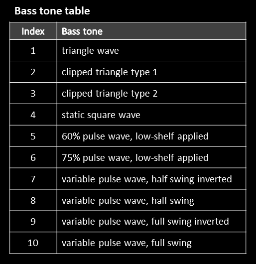
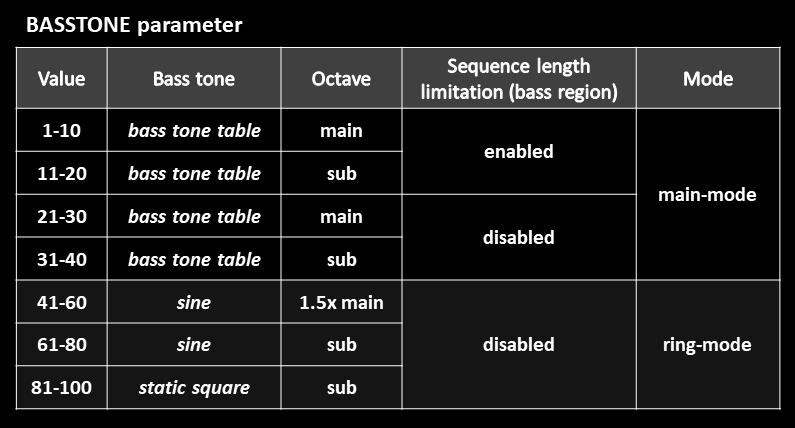
The next table illustrates the mapping of the BASSTONE parameter. For the value range 1-40 of the main mode, the bass tone table is repeated four times, once for each combination of octave and length-limitation settings. For parameter values 41-100, the oscillator operates in ring-(modulation)-mode using three different bass tones. For each setting, the parameter adjusts the phase offset using 20 different values.
PAR4: WARMTH [1…20]
Sets the impact of the low-shelf filter, emphasizing bass and low mid frequencies for a mellower sound. This filter is always applied on the sequence wave, but also (and only) on bass tones 5-6.
PAR5: LFO FREQ [0%…100%]
Adjusts the frequency of the internal LFO. For 0%, the LFO is bypassed.
PAR6: LFO AMT [-100%…100%]
Sets the modulation amount of the internal LFO on the pulse width. The LFO is reset with every note-on command of the corresponding voice. Note that bipolar values can be set, providing more flexibility regarding the start condition.
Pulse sequences with variable pulse width
Recall the basic principle of a sequence being divided into segments. In the case of a pulse sequence, each up-transition can be advanced to some extent, while each down-transition can be delayed correspondingly. This results in extended positive pulses and shortened negative pulses. Conversely, the positive pulses can be shortened while the negative pulses are extended. As a result, we obtain a generalized form of centered PWM when the pulse width is modulated. In general, the effectiveness of this PWM decreases with rising sequence length.
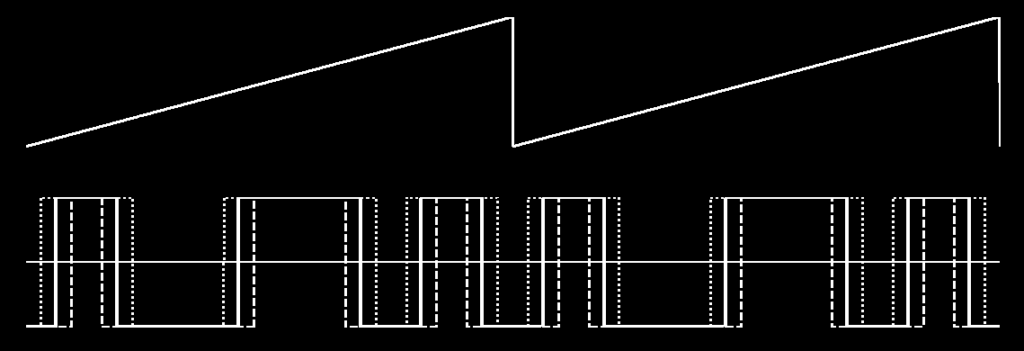

For SEQ5, a pulse sequence is routed through a digital low-pass filter to generate the oscillator signal. The filter offers both two-pole and four-pole modes, each with adjustable resonance, keyboard tracking, and drive. The pulse sequence was chosen as the sole input to ensure a bright, harmonically rich starting point.
The oscillator provides four wave modes, as detailed in the control section. In two of these modes, the pulse sequence is mixed equally with a simple square wave to reinforce the fundamental frequency and provide a more solid tonal foundation.
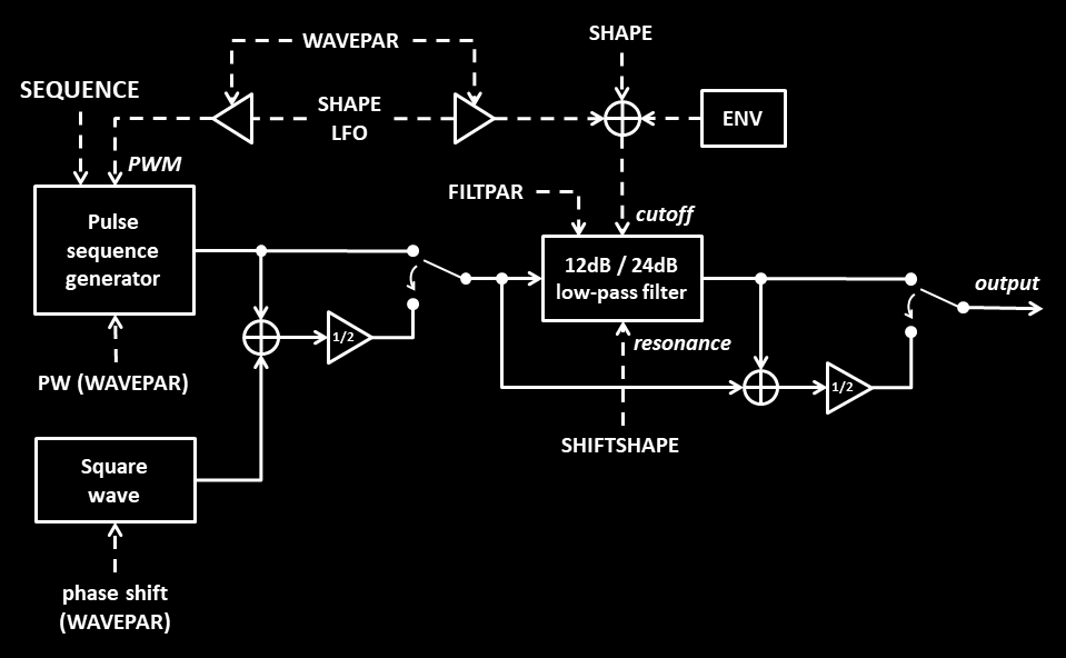
In theory, the digital filter with its dedicated envelope is a substitute for the analog section and allows the tamed oscillator to bypass the analog signal path altogether, so that the analog filter section can be exploited for the analog oscillators alone. This can be done by setting the standard pre/post filter option in the synth menu to “post”. If not bypassed, the digital and analog filter will both be applied on the sequence waveform, which is also usable, especially when two-pole mode is selected.
Alternatively, there is also a mixed-mode included where the unfiltered signal is mixed in equal parts with the filtered one, so that the final analog filter has more high frequencies to work with, provided that the user oscillator is routed through.
SEQ5: controls
SHAPE
Adjusts the cutoff frequency of the filter.
When SHAPE is positioned hard left and mixed mode disabled, for example when the init preset is applied, the sound will be very quiet, since most of the spectrum is filtered out.
SHIFTSHAPE
Sets the resonance of the filter. When positioned hard left, no resonance is applied.
SHAPE LFO
Depending on the mode, modulates the cutoff frequency and/or the pulse width of the sequence.
PAR1: SEQUENCE [1-101]
Selects one out of 101 sequences with given initial state and length, the same sequences as used for SEQ2.
PAR2: WAVEPAR [1-101]
The WAVEPAR parameter switches between four oscillator waveform modes and also applies some fine tuning of each waveform, according to the following table. For the last mode though, this parameter changes the LFO modulation and not the waveform. In this mode, the waveform consists of a standard square sequence with 50% pulse width which can be pulse-width modulated by the LFO for a more liquid sound. For higher parameter values, the pulse modulation amount is increased while the cutoff amount is decreased. At the corner values 91 and 101, only one type of modulation remains.
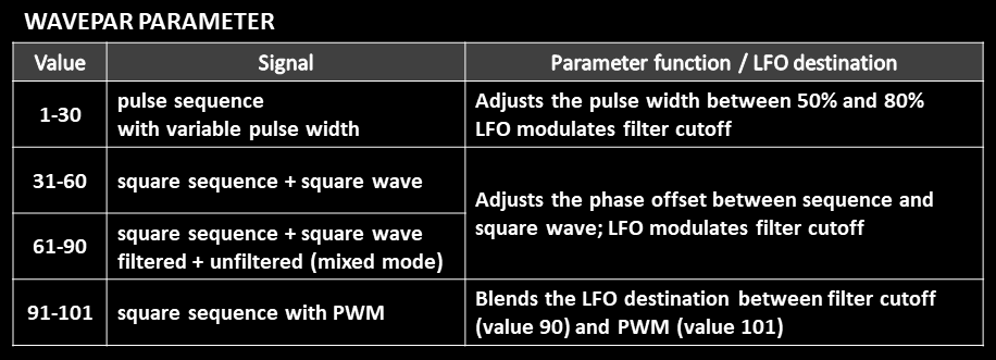
PAR3: FILTPAR [1-99]
This parameter defines the properties of the lowpass filter. Left and right digit of the parameter work independently.
The left digit switches between 12dB/dec- (values 0-4) and 24dB/dec-mode (values 5-9) and also adjusts the filter drive using the five values of each mode. Higher values apply more drive.
The right digit sets the amount of filter tracking with the key between 0% (values 0-1) and 100% (value 9) using 9 steps. Values 0 and 1 lead to the same result.
PAR4: ATTACK [0…100%]
Sets the attack time of the A/D-envelope.
PAR5: DECAY [0…100%]
Sets the decay time of the A/D-envelope.
PAR6: AMOUNT [-100%…100%]
Sets the envelope amount, which can have positive or negative values.
Note: for attack=0, decay=0, the envelope is deactivated.
SEQ6 focuses on linear FM with a sequence in the role of a carrier or modulator, but also includes a few non-sequence modes. The primary purpose is to use linear FM to change the timbre of a carrier wave while keeping this wave in tune. As usual for FM synthesis, the ratio between carrier and modulator also defines the character of the timbre. The oscillator offers ten different settings which include both sequence and non-sequence schemes. Since the control mappings change per setting, this oscillator model with all its tables can appear a bit complex at first. Hence, for the beginning, it is recommended to get accustomed to one mode at a time.
Oscillator modes
This section gives a quick overview of the implemented oscillator modes, which are treated as global settings selected by the WAVE parameter. The mapping of synth controls to signal parameters is specified in full detail in the control section in the form of tables. The tables also indicate which combinations in the diagrams are actually supported, since the number of synth controls imposes certain limitations. SHAPE LFO and envelope (ENV) also exist as modulation sources, but are not shown for simplicity. The basics of “relative FM” and “absolute FM” are described in the last section of this oscillator.
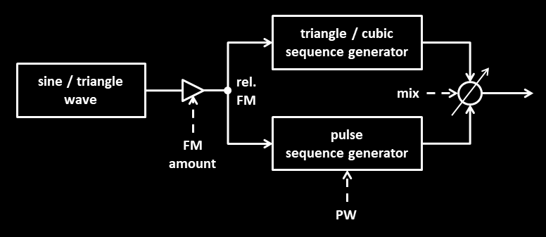
In sequence mode 1, a sine or triangle wave modulates a sequence using “relative FM”. The sequence output consists of a triangle or cubic sequence mixed with a pulse sequence of variable pulse width, so that the mix parameter effectively acts as a brightness control. Three modes (combinations) can be selected: a sine modulating a triangle/pulse sequence, a triangle modulating a cubic/pulse sequence, and a PWM mode, where a triangle modulates only the pulse sequence which can be PWM-modulated by the shape LFO.
The cubic wave sounds similar to a saturated triangle and offers more loudness. SHAPE LFO modulates either the FM amount or the pulse width in PWM mode, while the envelope always acts on the FM amount. The impact of FM is quite low for the basic wave, but, on average, increases with rising sequence length as the number of signal transitions during one waveform period goes up.
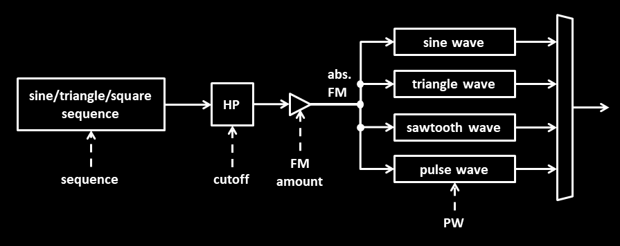
In sequence mode 2, a sine, triangle or square sequence is modulating a carrier using “absolute FM”. For this carrier, one of the usual basic waveforms can be selected. Six of the twelve possible combinations are supported, as shown in the wave table presented later. The sequence is highpass-filtered to ensure an average value of 0, avoiding detuning of the carrier. The highpass cutoff value can be adjusted by the user to be able to reduce the FM amount for low to mid notes. SHAPE LFO and ENV both modulate the FM amount.
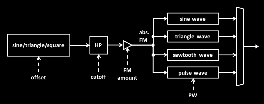
When the oscillator works in offset mode, which looks very similar to sequence mode 2, sequencing of the modulator is replaced with a simple phase offset control. A phase offset between carrier and modulator can be an effective means to change the resulting timbre, depending on the applied frequency ratio. The envelope can optionally alter the pitch of the modulator. This kind of pitch sweep depends on the FM amount and frequency ratio and sounds very different compared to an ordinary pitch sweep applied to the carrier. In addition, carrier and modulator can be detuned against each other. This option is available for all non-sequence modes.
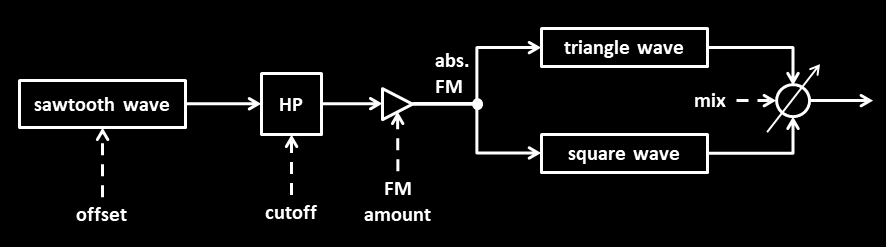
Sawtooth mode behaves similarly to offset mode, with the difference being that the modulator is always a sawtooth wave, while for the carrier you can fade between a triangle and a square wave. Like for sequence mode 1, this mix-parameter can be regarded as a brightness control. As before, the envelope can modulate either the FM amount or the modulator pitch.

PWM Mode 1 combines frequency modulation (FM) with pulse width modulation (PWM). In this mode, the envelope (ENV) modulates the FM amount, adding tonal variation and dynamic movement. Meanwhile, the SHAPE LFO modulates the pulse width. This combination can transform a standard PWM sound into something more complex and evolving.
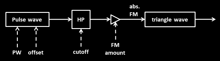
For PWM mode 2, the pulse wave becomes the FM source, modulating a triangle wave. If the pulse width is PWM modulated using the SHAPE LFO, the amount of FM modulation determines how much of that dynamic sound reaches the output. As before, the FM amount can be modulated by the envelope.
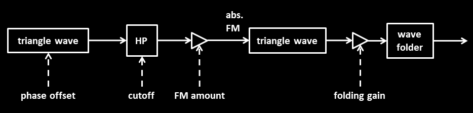
In triangle mode, a triangle wave modulates a triangle carrier, which then passes through a triangular wave folder. This wave folder works unipolar and avoids the alignment of the carrier onto n-ary frequencies which can appear with a bipolar wave folder. SHAPE LFO and ENV can alter either the FM amount or the folding gain, each handling a different target. In contrast to the other schemes, the HP cutoff frequency is selected with the WAVE parameter. In particular, the highpass filter can be bypassed altogether using the first setting.
SEQ6: controls
SHAPE
Adjusts the static frequency modulation (FM) amount.
SHIFTSHAPE
Depending on the mode, adjusts either the cutoff of the highpass filter, the pulse width or the phase offset of the modulator.
SHAPE LFO
Depending on the mode, the SHAPE LFO modulates either the FM amount or the pulse width.
PAR1: SEQ/MOD [1…101]
This is a multi-purpose parameter whose function depends on the mode and is defined in the following table. In FM-related sequence modes 1 and 2, SEQ/MOD selects the sequence. In offset and sawtooth mode, SEQ/MOD adjusts the phase offset of the modulator and also selects whether ENV modulates FM or the modulator pitch. In PWM modes 1 and 2, SEQ/MOD determines the pulse width. Finally, in triangle mode this parameter sets the amount of folding and switches between two modulation settings.
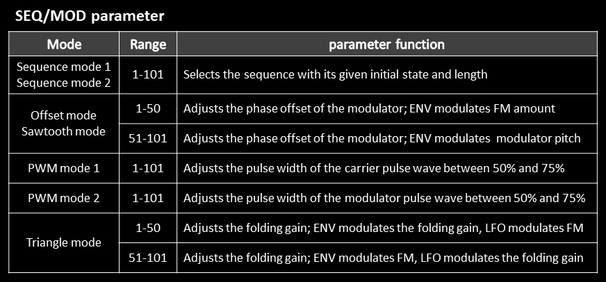
PAR2: WAVE [1…100]
There are 10 global oscillator settings that define the oscillator’s mode of operation. Each setting spans 10 consecutive values of the WAVE parameter. This parameter can be regarded as the central parameter of the oscillator. It selects the global setting and determines which function is assigned to each of the parameters SHAPE, SHIFTSHAPE, “SEQ/MOD” (PAR 1) and “FREQ” (PAR3), but also represents another independent parameter by itself through the 10 values per setting.
For a subset of three out of the ten oscillator settings, namely those involving sequence mode 2 and offset mode, a sub table is defined which determines the combination of carrier and modulator waveform. For simplicity, this table is called wave table.
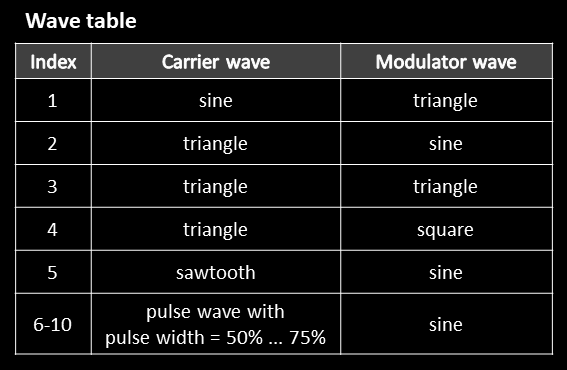
As shown above, a pulse carrier with a variable pulse width is part of the available carrier waveforms. The selected pulse width, in this case, cannot be modulated. For a PWM sound, choose one of the PWM modes. If a sawtooth shall be used as a modulator wave, choose sawtooth mode.
The wave table is embedded in the following global parameter table and appears for three settings. The WAVE parameter, besides switching between global settings, selects the index of the wave table, controls the mix between two waveforms, adjusts the phase offset between waveforms or sets the cutoff frequency of the high-pass filter, depending on the mode. The second part of the table provides an overview of the parameter mappings.
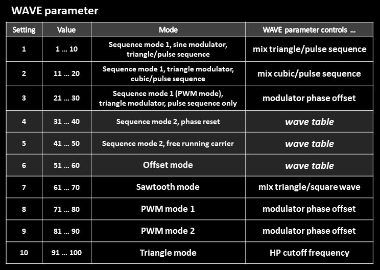
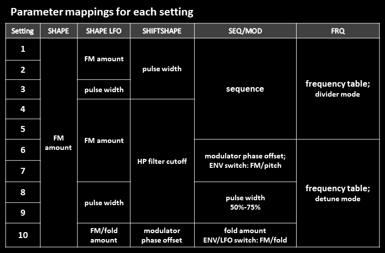
- The first two settings use sequence mode 1 and differ in the selection of modulator and carrier waveform.
- Setting 3, also using sequence mode 1, provides LFO-driven PWM for the FM-modulated pulse sequence as the only carrier waveform. This mode can be regarded as a third PWM mode, using sequencing.
- Settings 4-5 represent sequence mode 2 in two slightly different variations. When the key is striked, setting 4 always resets the phase of carrier and modulator to obtain a uniform sound. For setting 5, the carrier is free running, so that the timbre has some variation from voice to voice.
- Settings 6-10 directly represent offset mode, sawtooth mode, PWM modes 1-2 and triangle mode and are described in the introduction.
PAR3: FREQ [1…101]
The main purpose of the FREQ parameter is to define the frequency ratio between carrier and modulator, but it also offers a few extras and behaves differently in FM-related sequence and non-sequence modes.
The frequency table shown below determines the carrier-modulator frequency ratio, which has a high impact on the timbre when FM is active. For indices 1–12, the unmodulated carrier plays in the main octave, while for indices 13–24, it plays one octave lower (in the sub octave). The modulator frequency, on the other hand, is determined by the given C/M-ratio. For example, for a given C/M ratio of 1:4, the modulator plays 2 octaves above, while for 4:1, it playes two octaves below the carrier.
Now as soon as FM modulation is applied, the carrier becomes modulated, and for some ratios, the carrier is perceived as being shifted down by one or two octaves, depending on the numerator of the selected C/M ratio. If the numerator is 2, the carrier sounds like shifted down by one octave; if it is 4, it sounds like shifted down by two octaves. For a value of 1, the carrier remains in its original octave (which is either the main octave for indices 1-12 or the sub octave for indices 13-24 as stated earlier). The reason for this behavior is the effective period of the resulting wave, arising from the modulation process.
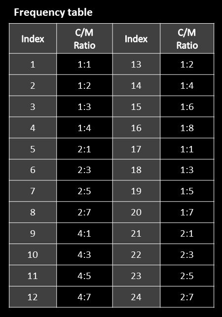
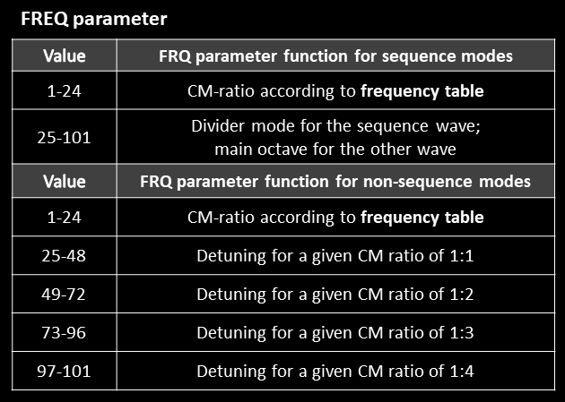
In practice, you can judge by ear instead of using the frequency table. Note that even C/M-ratios such as 1:2, 1:4, 1:6 lead to symmetric waveforms with a pronounced hollow sound, because only odd harmonics are generated.
The frequency table is embedded in the FREQ parameter table and only applies for indices 1-24, as shown above. When higher indices are selected, either divider mode or detuning mode is activated.
Divider mode
For FM-related sequence modes 1 and 2, once you have passed the frequency table and have reach parameter value 25, you have entered the experimental divider mode, or 1/N-mode, with N=1 for FREQ=25, N=2 for FREQ=26, etc. In this mode, the length of the sequence is extended by a factor of N, but without changing the segment duration. As a result, the waveform period is extended by a factor of N, and this leads to the sequence pitch being divided down by N. The pitch of the other wave always corresponds to the main pitch.
For example, if the original length was L=15, and we set N=8, the resulting length becomes LxN=120, and this sequence is pitched down by three octaves, since its frequency is divided by N=8.
Detuning mode
For non-sequence modes, parameter values 25-101 can be used to detune the carrier against the modulator for three different CM ratios—1:1, 1:2, and 1:3—with limited detuning available for a 1:4 ratio. Low to moderate detuning can produce nicely evolving sounds, whereas excessive detuning tends to shift bass notes upward, making the patch sound noticeably out of tune.
PAR4: ATTACK [0…100%]
Sets the attack time of the A/D-envelope.
PAR5: DECAY [0…100%]
Sets the decay time of the A/D-envelope.
PAR6: AMOUNT [-100%…100%]
Sets the envelope amount, which can have positive or negative values.
Note: for attack=0, decay=0, the envelope is deactivated.
Absolute and relative linear FM
For linear FM, keeping the pitch in tune can be accomplished with the carrier and modulator following simple frequency relationships, and with the modulator wave being DC-free. For basic symmetric waveforms such as triangle, sawtooth and square, the latter condition is met. For other modulators like sequences or non-symmetric pulse waves, a highpass filter in the modulation path can easily enforce this condition. As described before, this filter is inserted for various modes of the oscillator.
If the modulation amount has a scaling to make it proportional to the carrier frequency, it can be called relative FM. One can think of a maximum linear frequency deviation df caused by FM. For relative FM, this deviation scales with the carrier frequency f0, as shown for two cases in the Figure below. Due to the scaling, this type of linear FM produces a constant timbre across the keyboard. To avoid aliasing, the FM amount can be reduced for very high pitched notes, for which a change of the sound is not so obvious.
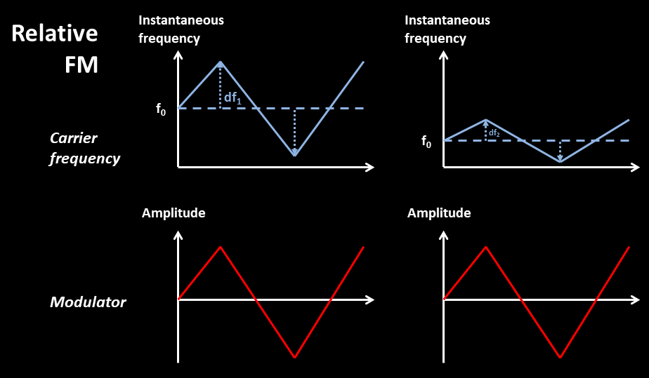
If the modulation amount is set independently of the carrier frequency, we can speak of absolute FM. For this type of linear FM, the maximum frequency deviation df has a fixed amount. Therefore, for high carrier frequencies, df might be only a small fraction of f0, while for very low frequencies, df might be larger than f0. For this reason, the impact of the modulation decreases with rising carrier frequency f0 and can be very high for low pitched notes in the bass region, so that the change in timbre varies across the keyboard. This fact can be regarded as a disadvantage. On the other hand, more aggressive FM amounts for bass and mid notes can be applied without running into aliasing problems for high pitched notes.
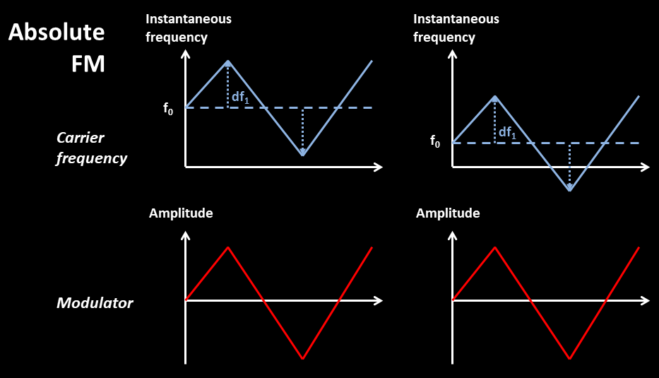
For this oscillator, both relative and absolute FM are used, but the latter for the majority of modes. To limit the FM amount in the bass region, the aforementioned high-pass filter is inserted in the modulation path, which ensures both a DC free operation and an FM limitation. The user can adjust the corner frequency, so that the filter becomes part of the sound design. The timbre will still change over the keyboard due to the introduced phase shift by the filter, but this can be regarded as part of the sound.
Through-zero FM (TZFM) and non-TZFM
Another aspect of linear FM is the modulation range. The modulated carrier frequency will fluctuate between a minimum and maximum value. If this minimum can be negative, we have through-zero FM. Normally, to hear a drastic change in timbre, TZFM is key, requiring the modulated carrier frequency to have negative values at times. A negative frequency would lead to some complications for sequenced carriers and has been avoided for them. Note that a sequence of sufficient length is a complex signal, often with many fluctuations, so that the higher modulation range of TZFM is not even required to get a stronger change in sound. In result, the FM modulation range has been restricted for the sequenced-carrier mode and extended to TZFM for the other modes.
Technical notes
All of the oscillators are based on the same DSP framework, applying oversampling and frequency-dependent waveform smoothing to avoid audible aliasing. For most oscillators, some slop and drift is incorporated to mimic the behavior of analog VCOs.
Regarding aliasing, the oscillator models CRUDE and CHAOS are exceptions. The CRUDE oscillator with its deliberate LOFI character can experience aliasing for high notes, depending on the settings. It has been designed with a different attitude. For the CHAOS oscillator, aliasing can be suppressed with the lowpass filter in the feedback path. The cutoff frequency is set by the user.
All oscillator models use the following available eight parameters:
PAR1–PAR6 shall denote the parameters which are accessed using menu diving.
SHAPE denotes the shape mod knob assigned to the digital oscillator and has a finer resolution.
SHIFT+SHAPE is the same knob, but used together with the SHIFT button.
SHAPE LFO represents the synth LFO when (a) this LFO is assigned to SHAPE using the front panel switch and when (b) the LFO includes the user oscillator, as can be set in the menu (selecting either all oscillators or only the user oscillator as a destination). Then it acts as a modulation source seen by the user oscillator. The intensity with positive or negative polarity is controlled via the INT knob and the optional SHIFT button. In general, the user has the choice between a global LFO or an LFO per voice, switchable using the LFO voice sync setting. For the XD, a simple linear envelope with attack=0 using the LFO sawtooth-setting, or attack=release using the LFO triangle-setting can be imitated with one-shot mode enabled and the settings “voice sync” = “off” and “key sync” = “on” in the LFO menu. In this case, the speed of the LFO defines the inverse of the release. This feature is essential for the oscillators which do not include an envelope. For the Prologue, this “envelope” will be repeated.
Regarding usability, the chosen design philosophy for many of the models has been to get the most functionality out of the general six parameters assigned to a user oscillator in the menu. This approach has sometimes led to “creative” workarounds which might seem a bit peculiar at first.
In particular, bipolar parameters are used in many cases which come with a small inconvenience. For the current release of the official Logue API, a small bug is still present which is related to bipolar parameters. When a user oscillator is freshly loaded for a new patch, the internal states of all bipolar parameters are at position “-100%” and not at “0%”, although “0%” is shown in the screen during the first menu iteration. Fortunately, this circumstance can be utilized to quickly reset each bipolar parameter to 0. This can be done during the first iteration only by simply incrementing each bipolar value from “0%” to “%1” and back to “0%”. If left unchanged, the parameter will remain and finally be shown at “-100%” which is usually not a good starting point. The advantages of bipolar parameters are manifold, allowing negative envelope amounts etc.